


Issue Summary:
- This month we cover an interesting situation in 1999 and later Mercury Cougars that can be caused by a defective radio.
- Persistent codes for throttle-position and/or vehicle-speed sensor on Nissan Quest/Mercury Villager can be caused by lower engine mounts.
- A number of factors can cause a shuttle-shift complaint in RE units behind 5.9-liter diesel engines that cycle in and out of lockup at highway speed.


In 1999 and later Mercury Cougars, the vehicle speed displayed in the dash may be either erratic or not present. The data stream viewed through a scan tool is consistent with that observed in the dash.

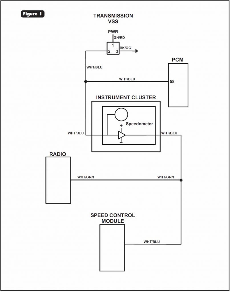
One cause for this concern is a defective radio. Most 1999 and later Cougars are equipped with a higher-content package. Part of this package provides a vehicle-speed signal to the radio. Its purpose is to raise the volume proportionally with vehicle speed to compensate for the increased road noise at higher driving speeds. The vehicle-speed signal is sent simultaneously to the powertrain control module (PCM) and speedometer. From the speedometer it is sent to the radio (see wiring diagram in Figure 1). When the radio malfunctions, it affects the vehicle-speed signal to both the speedometer and PCM. This concern also will affect shift strategy.

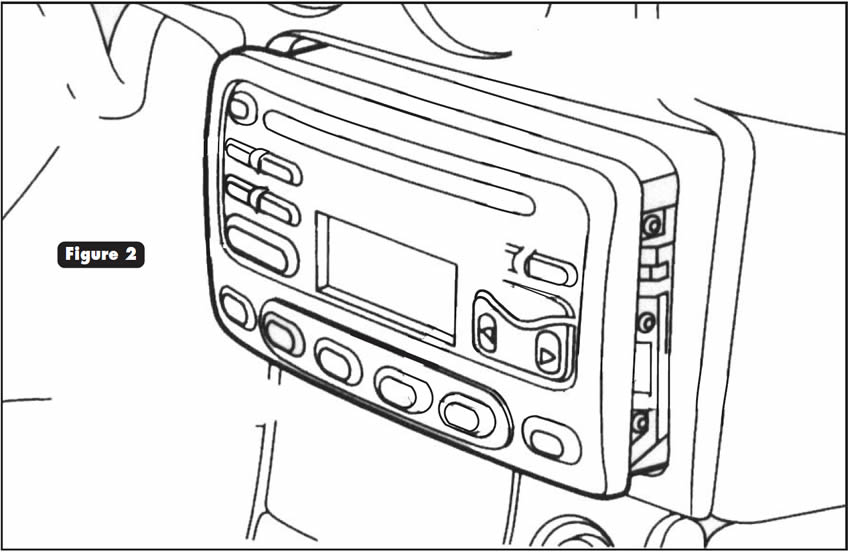
Unfasten the radio so you can pull it forward out of the dash (see Figure 2).
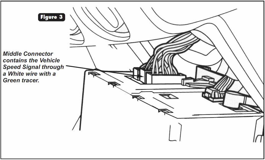
There is enough wiring to gain access to the rear of the radio (see Figure 3). You will find three connectors that plug into the back of the radio. The middle connector should have a white wire with a green tracer. Unplug this connector and drive the vehicle. If the vehicle-speed-signal problem no longer exists, the radio is defective and will need to be replaced.


Persistent codes for throttle-position and/or vehicle-speed sensor. This complaint also may be accompanied by stored air-flow-meter or EGR-sensor codes in the engine computer. Intermittent inhibitor-switch malfunctions also may be present.
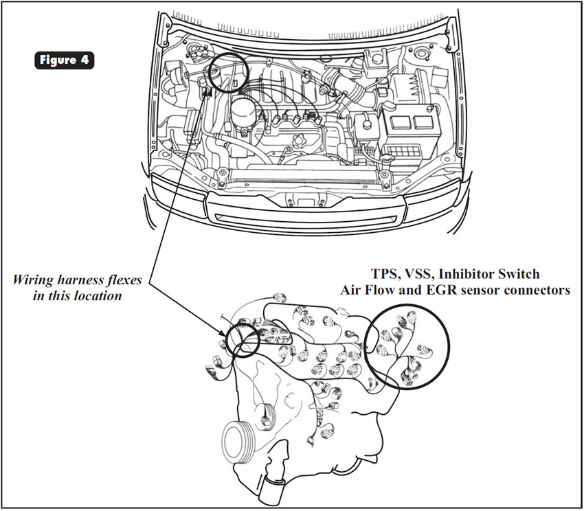
Lower engine mounts have been known to soften or break, allowing excessive engine rotation with increased torque. If this engine-rotation condition is permitted to continue for a long time, a junction in an engine-compartment wiring harness containing the TPS, VSS, EGR, AFM and inhibitor-switch wiring circuits can flex frequently (see Figure 4). As a result, these wires become fatigued and compromised, producing erratic and chronic faults.
Repair the mounts and the damaged wire or wires related to the complaint.


RE units behind 5.9-liter engines cycle in and out of lockup at highway speed.
There are many possibilities, such as a malfunctioning brake-switch or brake-support bracket, and temperature sensors, alternators, throttle-position sensors and vehicle-speed sensors to name a few. Chrysler has even issued a reprogramming procedure (Bulletin #18-02-99) for 1996 and later vehicles that compensates for alternator or TPS noise to correct this complaint. TCC shuttle while the vehicle is being driven with a scan tool attached to the data-link connector also has been reported. The problem goes away when the scan tool is unplugged.
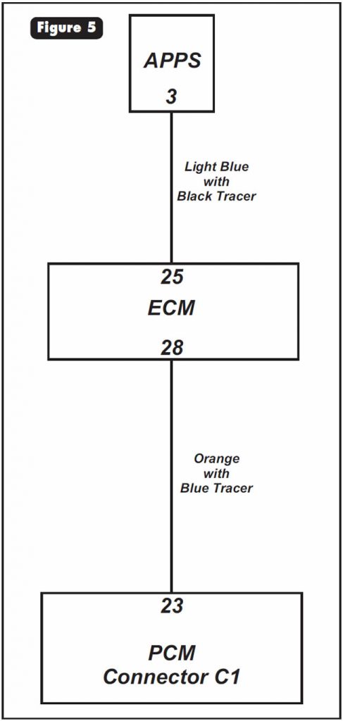
One other possibility that can be overlooked is a defective ECM in 1998 and later vehicles. These vehicles are equipped with an accelerator-pedal-position sensor (APPS) rather than a TPS. The APPS sends a typical TPS signal to the ECM, and the ECM sends that signal to the PCM. Should the ECM malfunction, the PCM receives an incorrect signal, causing the shuttle-shift complaint (see Figure 5).
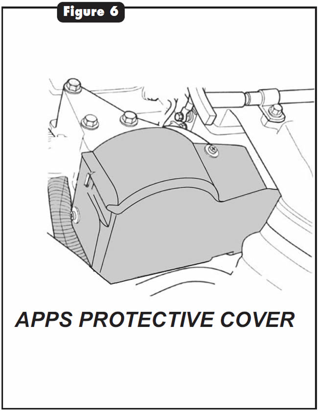
The APPS is at the front of the engine compartment on the driver side under a plastic protective cover (see Figure 6).
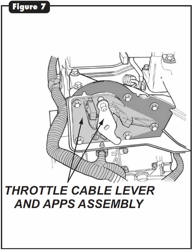
With the cover removed (see Figure 7), you can see how the accelerator-pedal cable operates a throttle cam that is attached to a mounting plate.
The APPS is on the back side of this assembly (see Figure 8).
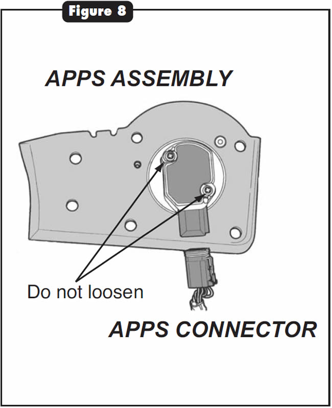
Figure 9 identifies terminals in the APPS connector.
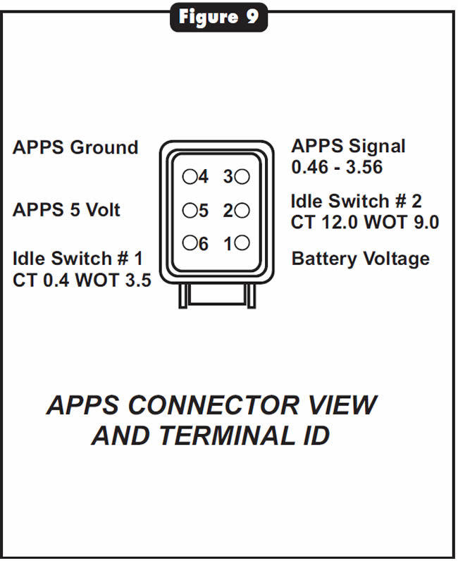
Terminal 3 sends a typical throttle-opening signal voltage ranging from 0.5 volt to 3.5-4.0 volts to terminal 25 in the ECM (see Figure 10).
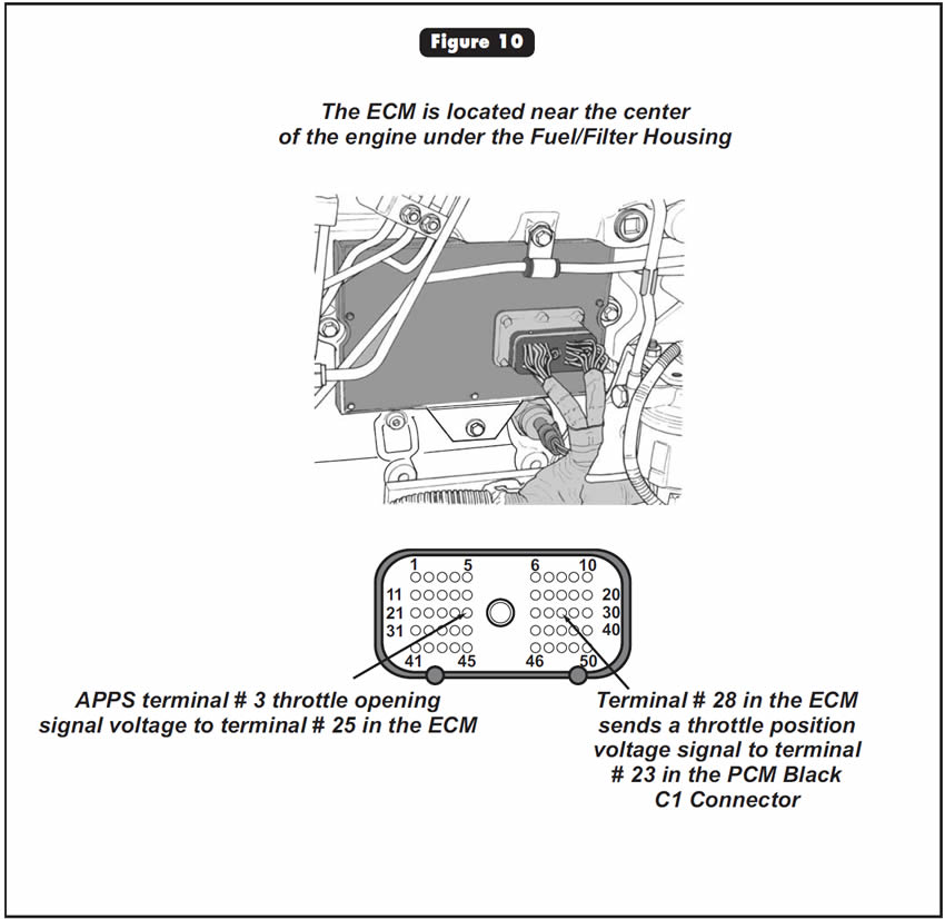
The ECM in turn sends that same signal to the PCM, from ECM terminal 28 to PCM terminal 23 in the C1 black connector (see Figure 11).
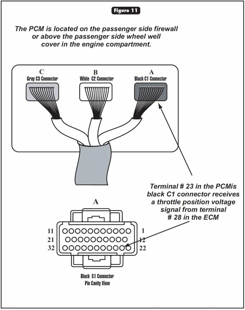
Simply inspect the voltage from the APPS to the ECM to ensure that the APPS is functioning correctly. Then inspect the signal from the ECM to the PCM. If the signal is incorrect, the ECM will need to be replaced. For further verification that an ECM needs to be replaced, cut the wire entering terminal 23 in the PCM’s black C1 connector. Run a jumper lead from terminal 3 in the APPS connector to terminal 23 in the C1 connector. If the direct signal from the APPS into the PCM corrects the problem, the ECM has been confirmed faulty.
Special Note:
The APPS comes mounted on a plate as an assembly (see Figure 8). Loosening the two attaching screws in an attempt to remove the APPS from the mounting plate will alter the APPS calibration, which will result in drivability complaints. The cost of the sensor is about $170.

June 2002 Issue
Volume 19, No. 6
- 1999 and Later Mercury Cougars: Erratic or No Vehicle-Speed Display
- Nissan Quest/Mercury Villager: Harness Fatigue
- RE-Series Units Behind 5.9-Liter Cummins Diesel: Torque-Converter Clutch Cycles In and Out


