Technically Speaking
- Subject: Internal components
- Unit: 2ML70 hybrid
- Vehicle Applications: 2008 Chevrolet Tahoe and GMC Yukon; 2009 Cadillac Escalade
- Essential Reading: Rebuilder, Diagnostician
- Author: Wayne Colonna, ATSG Transmission Digest Technical Editor
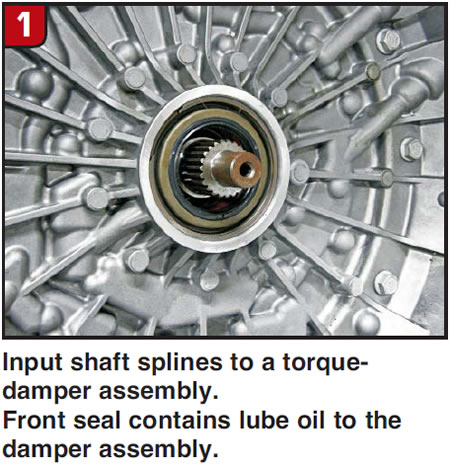
As promised, we are back to take a look at the inside of this 2ML70 hybrid two-mode RWD transmission. When you look at the front of this transmission it almost appears to be receiving input torque from the gas engine through a conventional torque converter (Figure 1), but that is not the case. Power from the engine is delivered through a torque-damper assembly that is bolted to the crank and splines to the input shaft and pump. The reason for the front seal is that cooler return oil is supplied to the assembly through the pump to keep its damping parts lubricated.
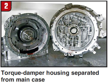
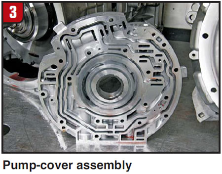
When the torque-damper housing is unbolted and removed from the main case, you can see the main pump assembly bolted to the back side of it (Figure 2). The pump cover containing the pump’s pressure-regulator (PR) valve, the auxiliary pump’s PR valve, and a lube and cooler bypass separates from the housing as seen in Figure 3.
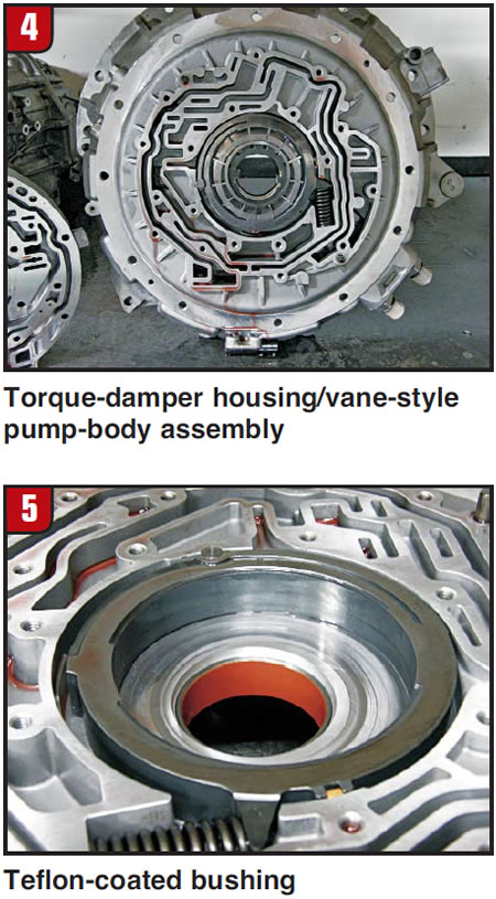
The housing contains a typical vane-style pump (Figure 4) but it also contains something not so typical. The bushings used in this transmission, starting with the pump (Figure 5), have a type of coating on them we have not seen before as evidenced by the bright-orange color. This appears to be a Teflon coating, and I assume that it has something to do with preventing electrolysis damage to the bushings, since this is a “highly electrified” transmission.
Once the damper housing and pump assembly is removed, you can see that the input shaft is also the internal ring gear for what is called the “Planetary Assembly 1st Position” (Figure 6). The carrier splines to what is called the main shaft, and the sun gear splines to the sun-gear shaft first position.
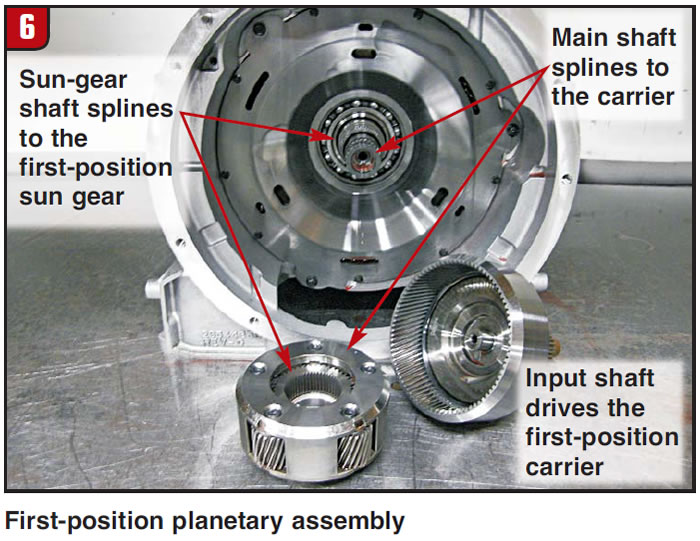
Now, this becomes interesting, because the first-position motor/generator that is next in line to come out of the transmission (figures 7 and 8) splines to this shaft also.
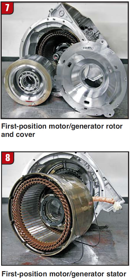
More specifically, it is the rotor (Figure 7) in the motor assembly that splines to the sun-gear shaft (Figure 9). This shaft is also the internal ring gear for the center planetary (second-position planetary assembly) and is also the hub for the 1-3 clutches.
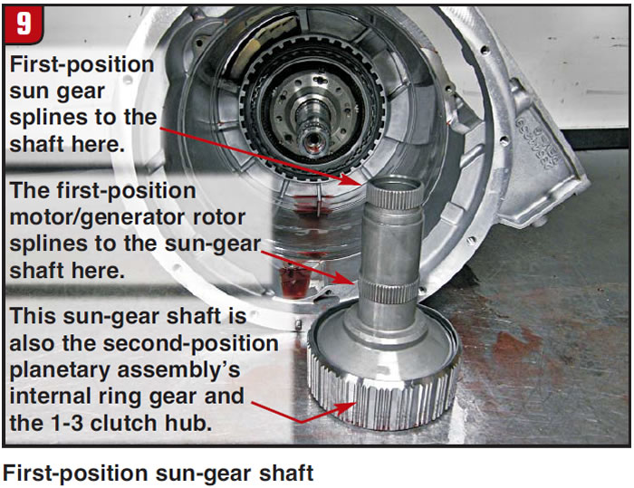
So what does all this mean? I did write a little about this in part 1, but rather than bore you with what is being driven and what is turning when, let’s just say that this is a very active shaft with multiple purposes. The motor/generator, for example, can drive this shaft, or the shaft can drive the rotor to generate electricity. With just a small glimpse of its function, can you imagine the problems that might arise should the splines on the shaft for the rotor strip out?
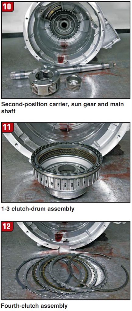
Next out of the case is the main shaft, sun gear 2nd position, the carrier assembly (Figure 10) and the 1-3 drum (Figure 11), followed by the fourth brake clutches (Figure 12).
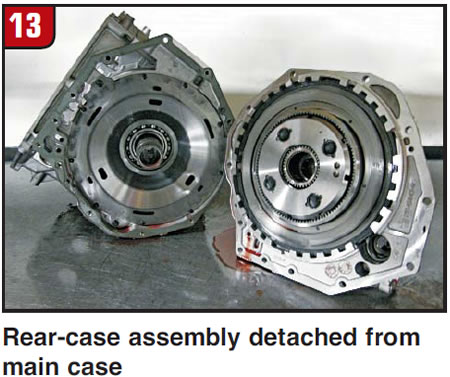
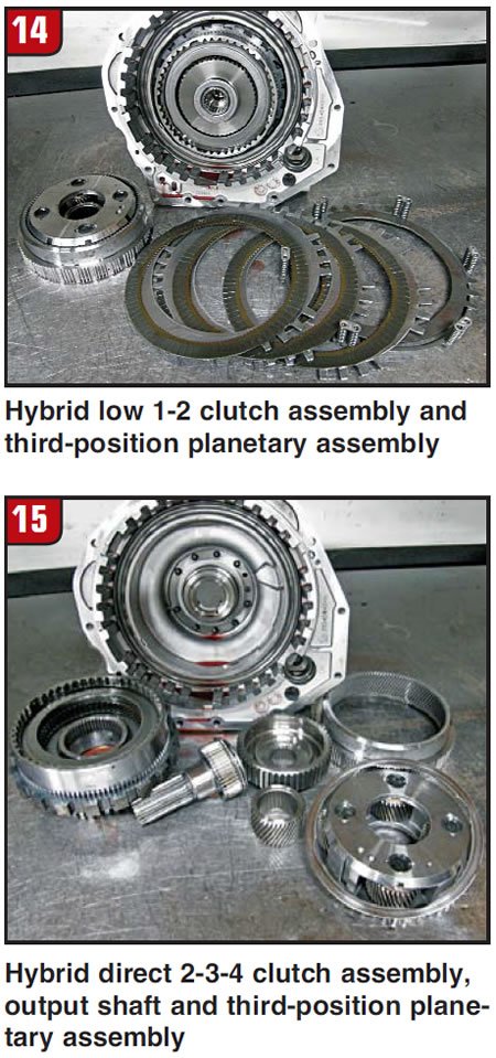
Inside the rear-case assembly (Figure 13) is the hybrid low 1-2 clutch assembly (Figure 14), the hybrid direct 2-3-4 clutch assembly (Figure 15) and third-position planetary assembly.
Looking back now, at the rear of the transmission is the sun-gear shaft third position (Figure 16).
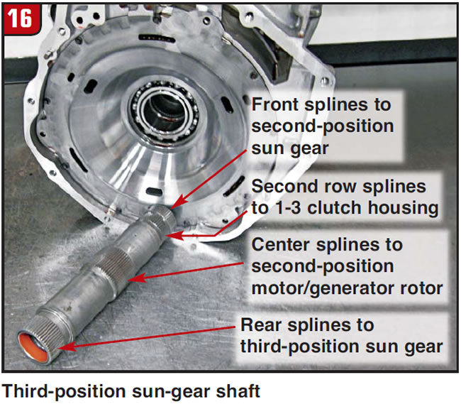
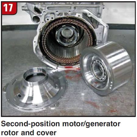
Just like the sun-gear shaft first position, this shaft also serves multiple purposes. It splines to the 1-3 clutch housing, the sun-gear second position, the sun-gear third position and the second-position motor/generator rotor (Figure 17). And as with the first-position motor/generator, this second-position motor/generator can drive this shaft or the shaft can drive the rotor to generate electricity.
You may have noticed in Figure 8 that when the stator portion of the first-position motor/generator was removed from the case, two droopy-looking O-rings came out with the stator.
I was taking this unit apart with Robbie Ferguson from Alto, and we both thought: “How odd is this? How in the world did this slide out without rolling these rubber rings and ripping them, and how would you ever get them back in?”
So we decided to carefully and very slowly remove the second-position motor/generator stator and watch what happens. As you can see in Figure 18, once the stator cleared the case this O-ring got happy.
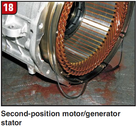
Perhaps there is some Viagra in the fluid. And actually that is what I believe to be the case here, in that the fluid and/or heat caused the seals to swell. I say that because the manufacturer’s instruction to install the motor/generator is to use special tool DT-47821 Motor Lift and place the assembly into the case as one unit (the stator, rotor and cover). New seals are to be in place, using transmission assembly gel as a lubricant. For this to happen, the seals cannot be the size you see them in figures 8 and 18. These seals contain fluid that is sent to the outside of both motor/generators to be used for cooling. Should they fail to contain that oil, the motors may overheat.
Now that we have seen the inside of this transmission, next month we will look at just a few more details that will round out a fairly comprehensive view and understanding of this new unit.
Once more I thank Alto for the use of this transmission.