Technically Speaking
- Subject: Design and operation
- Unit: 2ML70 hybrid
- Vehicle Applications: 2008 Chevrolet Tahoe and GMC Yukon; 2009 Cadillac Escalade
- Essential Reading: Rebuilder, Diagnostician
- Author: Wayne Colonna, ATSG, Transmission Digest Technical Editor
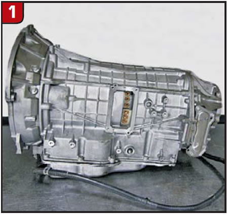
GM’s 2ML70 hybrid transmission (Figure 1) is a four-speed unit with fourth gear being overdrive. Applications include the 2008 Chevrolet Tahoe and GMC Yukon and the 6.0-liter 2009 Cadillac Escalade. It also was used for a short time in the 2009 5.7-liter Chrysler Aspen and Dodge Durango. BMW uses the two-mode 2ML70 in its ActiveHybrid X6, and Mercedes-Benz also uses it.
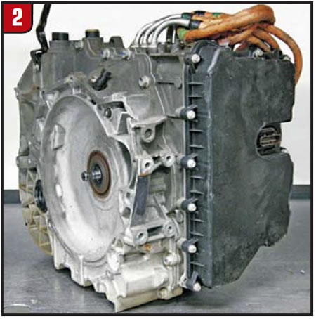
There is also a front-wheel-drive version of this hybrid transmission (Figure 2), and it is on the road in some 2.4-liter 2009 Saturn Vues. The rear-wheel-drive 2ML70 transmission is not difficult to tear down and work on. The front-wheel-drive version is a completely different story. If you have already tackled the rear-wheel-drive version, don’t be fooled into thinking the front-wheel-drive unit will be as easy to work on. We’ll provide an inside look at the front-wheel-drive version in a future issue of Transmission Digest after we examine the 2ML70.
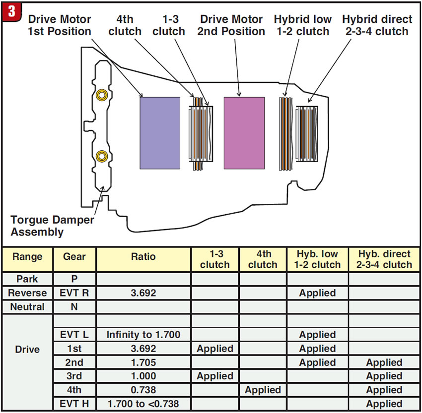
Inside this transmission are three planetary assemblies, four clutch packs and two motor/generators with torque being delivered to the transmission through a damper assembly. Figure 3 provides a simple clutch and motor/generator application chart.
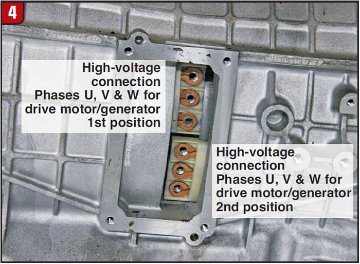
During disassembly, the first motor/generator you would find is simply called “Drive Motor Assembly 1st Position.” The second motor/generator you would encounter is – you guessed it – “Drive Motor Assembly 2nd Position.” Each of these motor/generators is basically made up of a large cylindrical coil called a stator that has the high-voltage wires attached to it (Figure 4). Inside each of these two cylindrical coils is a large internal drum called a rotor. In Part 2 of this series we will get to see the inside of this transmission.
Now put up with me for just one paragraph as I quickly explain how the ankle bone is connected to the leg bone, for it does have a purpose. The rotor in the 1st-position drive-motor assembly splines to the center of a shaft that splines into the front sun gear, and at the opposite end is the “hub” for the 1-3 clutch assembly. The rotor in the 2nd-position drive-motor assembly splines to the center of a shaft that splines to the 1-3 clutch “drum” and middle sun gear as well as to the rear sun gear at the opposite end of this shaft. Each of these motor/generators can either be a motor driving its respective parts of the drivetrain or be driven by them to generate electricity.
The purpose of explaining this is so that you can get a basic idea as to how these motor/generators interact with the internal parts of the gearbox. The stator and rotor produce a magnetic field that can drive the rotor, which drives a shaft inside the transmission; in turn, when the shaft drives the rotor, the magnetic field can be used to generate electricity.
Drive motor 1 is used to provide fourth gear when the engine is turned off. It also provides engine braking in first gear when the vehicle is coasting to a stop, at which time it generates electricity used to charge the hybrid batteries. Another job this drive motor has is to start the engine. If this motor/generator becomes inoperative, you will not be able to start the vehicle, as it is the only means to crank the engine.
Drive motor 2 is used to provide reverse and 1st gear when the engine is off. This motor also generates electricity when it is used to provide engine braking on coast. If this motor/generator becomes inoperative, you will not be able to move forward or backward when the engine is off.
From all that I have read on this unit, even though GM says you will not have forward or reverse when the engine is off, it appears to me that you will not have reverse if this motor/generator is inoperative, regardless of whether the engine is running. It is drive motor 2 that will drive the sun-gear shaft in the reverse direction while the low/1-2 clutch holds a ring gear stationary, completing the reverse power flow to the output shaft. If this motor is down, there does not appear to be a clutch in play that will do what this motor/generator can do. So even if the engine is running, there will be no reverse.
Besides high-voltage wires being attached externally to this transmission there are four other wiring connections, identified in Figure 5. The X176 pass-through connector and internal harness attaches to the motor/generators and the internal mode switch (IMS). The external harness connects primarily to the power inverter module (PIM) under the hood.
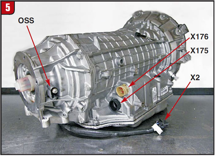
Similar to the configuration of the 6L80, the solenoid body and TCM are one assembly mounted inside the transmission. The X175 connector is the connector providing power, ground and CAN-bus wiring to the TCM. The output-shaft speed sensor (OSS) passes through the X176 connector and is directly wired into the TCM internally.
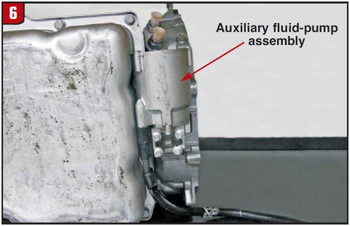
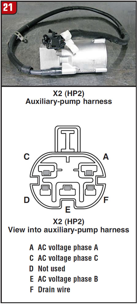
The fourth connector, X2 (HP2), is for the auxiliary fluid pump (Figure 6). This electrical pump is used to provide pump pressure when the engine is not running. GM refers to the engine as ICE (internal-combustion engine) and the operation of the electrical motor/generators as EVT mode. When ICE is running, the transmission’s main vane-type pump provides pressure for the transmission. When the vehicle is in EVT mode, ICE off, the auxiliary electrical pump provides the fluid pressure.
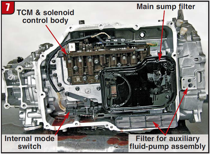
When you remove the pan there will be two filters: one for the typical vane pump and the other for the auxiliary fluid pump (Figure 7). The TCM and solenoid-body assembly also comes into view.
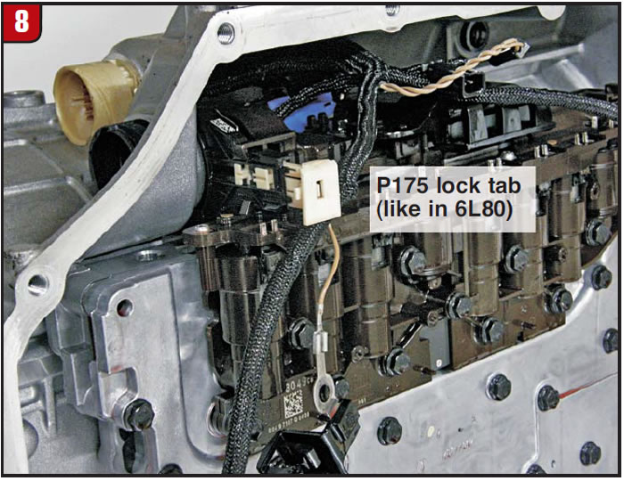
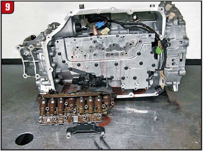
And just as in the 6L80, you need to lift a locking tab to release the TCM’s pass-through connector from the case (Figure 8). Figure 9 shows which bolts to remove to lift the TCM out of the transmission.
With the valve body removed, you can see the internal harness going to the X176 connector (Figure 10).
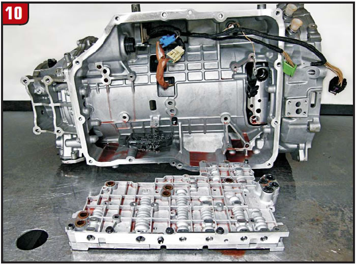
Figure 11 shows this harness removed with each of the connectors identified.
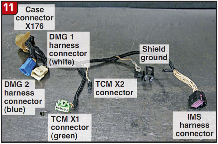
Figure 12 provides terminal identification for the X176 connector and the two internal motor/generator connectors.
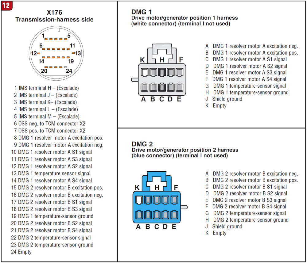
Figure 13 is a close-up view of the TCM/solenoid-body assembly’s X175 connector, and Figure 14 lists all the terminals that could be identified.
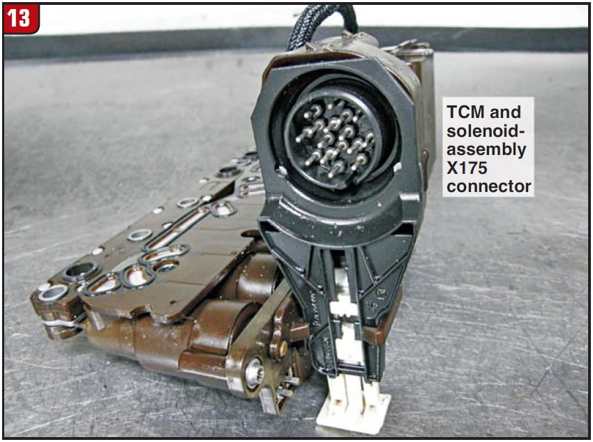
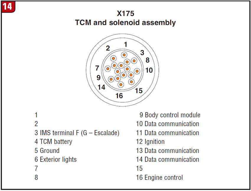
Figure 15 identifies solenoid and pressure-switch locations.
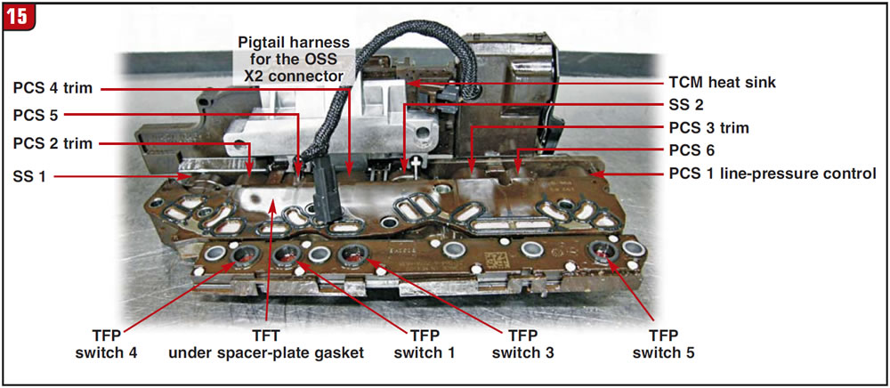
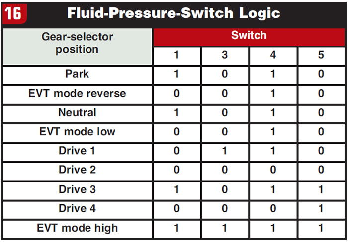
Figure 16 provides a pressure-switch logic table for diagnostic purposes with the use of a capable scan tool.
There is also a close-up view of another connector location on the TCM in Figure 17 where through the internal wiring harness this is connected to the Internal Mode Switch (Figure 18).
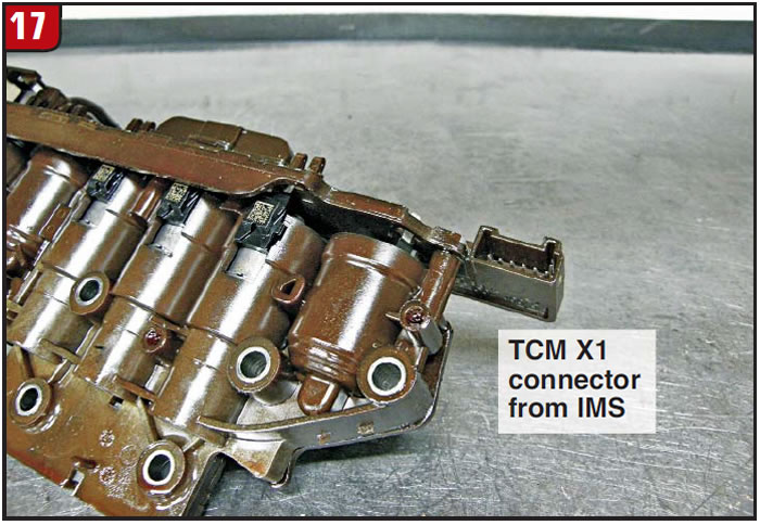
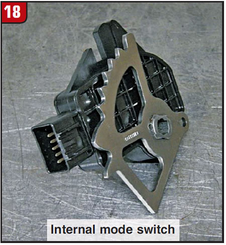
Figure 19 provides terminal identification for both the IMS and where it attaches to the TCM.
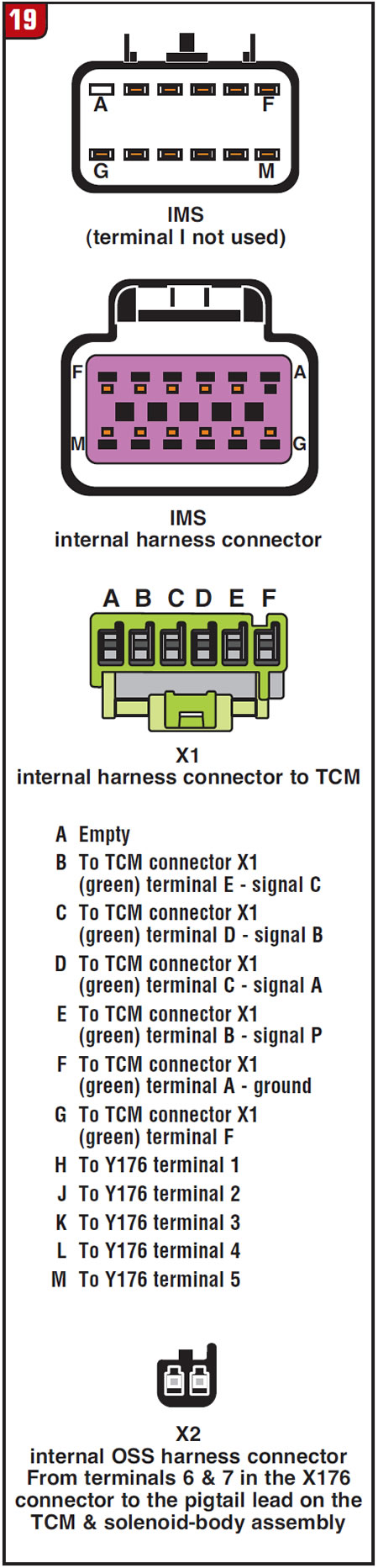
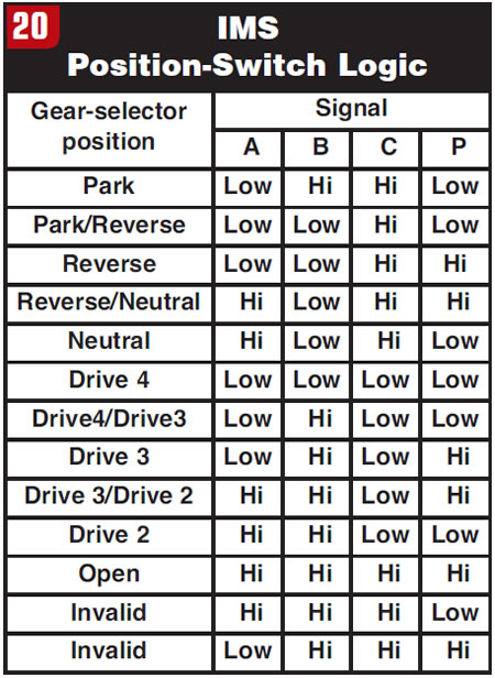
Figure 20 is the IMS logic chart, which can be used for diagnostics with a capable scan tool.
I’ll make a brief observation here about the IMS. There is limited information about this transmission in terms of really clear wiring diagrams. From what wiring schematics I have been able to locate, I have identified these terminals as best I can. What puzzles me is that the wiring for Cadillac Escalades shows IMS signals being provided directly to the power inverter module (PIM) under the hood through the X176 connector (Figure 12). It did not reveal any signals going to the TCM. Yet with Yukon and Tahoe vehicles it shows that the IMS signal is sent directly into the TCM through the connector shown in Figure 17. It did not reveal any signals being provided to the PIM.
Does this mean that there are two different internal mode switches, one for Cadillac and another for GMC and Chevrolet? I do not know. The unit I had the opportunity to work with was from a Tahoe, and the IMS signals to the TCM functioned as the logic chart in Figure 20 shows. The pins for the IMS going to connector X176 did not. Time will reveal what I am not totally clear on at the time of writing this article. What is for sure is that the internal harness will work in both Cadillac and GMC/Chevrolet vehicles.
Last but not least, Figure 21 identifies the terminals for the auxiliary pump. Next month we will look at the inside of this transmission and discuss the unit’s operation with a bit more detail.
For those who may be interested, this year’s ATSG “Great Tech Again in 2010” training seminar will include a detailed and informative presentation on safety procedures for removal of hybrid transmissions from various manufacturers’ vehicles. This is a seminar you should not miss, especially these days when we all need more work. Why turn a job down when you do not need to – especially one involving this transmission, a very nice unit to work on.
In writing an article like this, having a transmission goes a long way in being able to provide great visuals to aid in understanding. For this reason I thank Robbie and the good folks at Alto Products for lending this transmission to ATSG.