

Issue Summary:
- A 1993 or later Chrysler front-wheel-drive car or van may have a complaint of no speedometer operation and may have all the PRNODL lamps illuminated.
- Some 1999-2000 vehicles equipped with the 42RE/46RE may exhibit a harsh engagement in reverse.
- A 1996 or later Jeep or Dodge truck with an RE transmission may exhibit complaints of falling out of 4th gear and loss of TCC application. On diesel applications, the transmission may be stuck in 3rd gear and governor pressure may be 70 psi in Park.


The vehicle may have a complaint of no speedometer operation and may have all the PRNODL lamps illuminated. When you try to scan the TCM, the scan tool indicates, in the “Modules Responding” screen, that the TCM is not responding. A scan of the PCM may reveal zero mph, and code P0500 for loss of vehicle-speed signal may be stored.

A faulty output-speed sensor or its circuit, a loss of power to the TCM at terminal 11, a TCM that has not had the “pinion factor” flashed, a faulty TCM, a faulty PCM or a fault in the electronic analog instrument cluster.
Principles of operation: The example used here is a 1997 Dodge Caravan with a 3.8-liter engine and 41TE transmission. As shown in the wire diagram in Figure 1, the PCM provides a 5-volt signal from terminal 66 of the PCM to terminal 58 of the TCM. As the vehicle begins to move, the TCM, using its internal buffer, provides a square-wave signal to the PCM that is proportional to vehicle speed by pulsing the 5-volt power supply between ground and 5 volts. The PCM monitors and interprets this pulse into miles per hour, then broadcasts the signal over the communication network to all other modules requiring this signal.
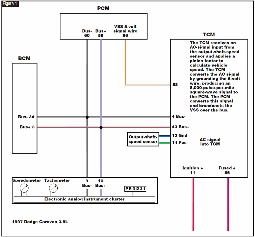

Check the signal from the output-speed sensor at terminals 13 and 14 of the TCM with your meter set on hertz (Hz) or with a scope. You should see a reading ranging from about 2.3 Hz at 10 mph to about 800 Hz at 40 mph, or scan other modules to see whether they display vehicle speed.
A reading within this range would mean the speed sensor and the TCM are not the cause of the problem. You also can check the 5-volt circuit at TCM terminal 58 for the toggle between 5 volts and zero. Be sure to turn the wheels very slowly when checking this signal, or the meter display will freeze, leading to an incorrect diagnosis.
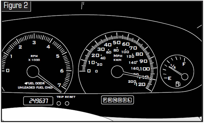
On vehicles equipped with a transmission-range sensor, when the TCM is causing the loss of VSS signal, all the PRNODL lamps may be illuminated as shown in Figure 2. Before condemning the TCM, connect a direct 12-volt jumper lead to TCM terminal 11. If this cures the problem, replace the ignition switch. Do not leave the jumper lead installed, and remove the jumper lead before turning the ignition off when this test is complete.
Check to see that the correct pinion factor is installed.
At this point the PCM or the electronic analog instrument cluster may be at fault. Diagnostics for these systems follow:
Verify power and grounds at the PCM, then perform the self-diagnostic routines for the electronic analog instrument cluster. If code 940 comes up during the instrument-cluster tests, the PCM is the probable cause of the previously mentioned complaints.
Self-diagnostic tests for electronic analog instrument cluster (refer to Figure 2):
Code Retrieval
- Have the ignition off.
- Press and hold the TRIP and RESET buttons simultaneously.
- While holding the TRIP and RESET buttons down, turn the ignition on.
- Continue to hold the TRIP and RESET buttons down until the odometer window displays the word “CODE.”
If no problem has been detected, a “999” will appear in the odometer window. If a fault is detected, the following is a list of codes that might be displayed in the odometer window:
- 110 = Cluster Memory Fault
- 111 = Cluster Calibration Fault
- 905 = No CCD Bus Message from TCM 921 = Odometer Fault from BCM
- 940 = No CCD Bus Message from PCM
After the codes have been displayed, the instrument cluster will enter the following four sequential test modes:
- CHEC – 0 = Dim test (the instrument-cluster lights should dim) CHEC – 1 = Calibration test (see accompanying chart)
- CHEC – 2 = Odometer test (each digit should illuminate)
- CHEC – 3 = Electronic transmission-range-indicator segment test (each segment of each digit should illuminate)
CHEC – 1 calibration test:
Speedometer
- 1 . . . . . . . . . . . . . . . . . . . . . . . . . . . . . .0 mph
- 2 . . . . . . . . . . . . . . . . . . . . . . . . . . . . .20 mph
- 3 . . . . . . . . . . . . . . . . . . . . . . . . . . . . .55 mph
- 4 . . . . . . . . . . . . . . . . . . . . . . . . . . . . .75 mph
Tachometer
- 1 . . . . . . . . . . . . . . . . . . . . . . . . . . . . . . .0 rpm
- 2 . . . . . . . . . . . . . . . . . . . . . . . . . . .1,000 rpm
- 3 . . . . . . . . . . . . . . . . . . . . . . . . . . .3,000 rpm
- 4 . . . . . . . . . . . . . . . . . . . . . . . . . . .6,000 rpm
Fuel Gauge
- 1 . . . . . . . . . . . . . . . . . . . . . . . . . . . . . .Empty
- 2 . . . . . . . . . . . . . . . . . . . . . . . . . . . . . .1⁄8 Full
- 3 . . . . . . . . . . . . . . . . . . . . . . . . . . . . . .1⁄4 Full
- 4 . . . . . . . . . . . . . . . . . . . . . . . . . . . . . . . .Full
Temperature Gauge
- 1 . . . . . . . . . . . . . . . . . . . . . . . . . . . . . . . .Cool
- 2 . . . . . . . . . . . . . . . . . . . . . . . . . .Low Normal
- 3 . . . . . . . . . . . . . . . . . . . . . . . . .High Normal
- 4 . . . . . . . . . . . . . . . . . . . . . . . . . . . . . . . .Hot
These checks determine only whether the instrument cluster needs to be replaced.


Some 1999-2000 vehicles equipped with the 42RE/46RE may exhibit a harsh engagement in reverse.
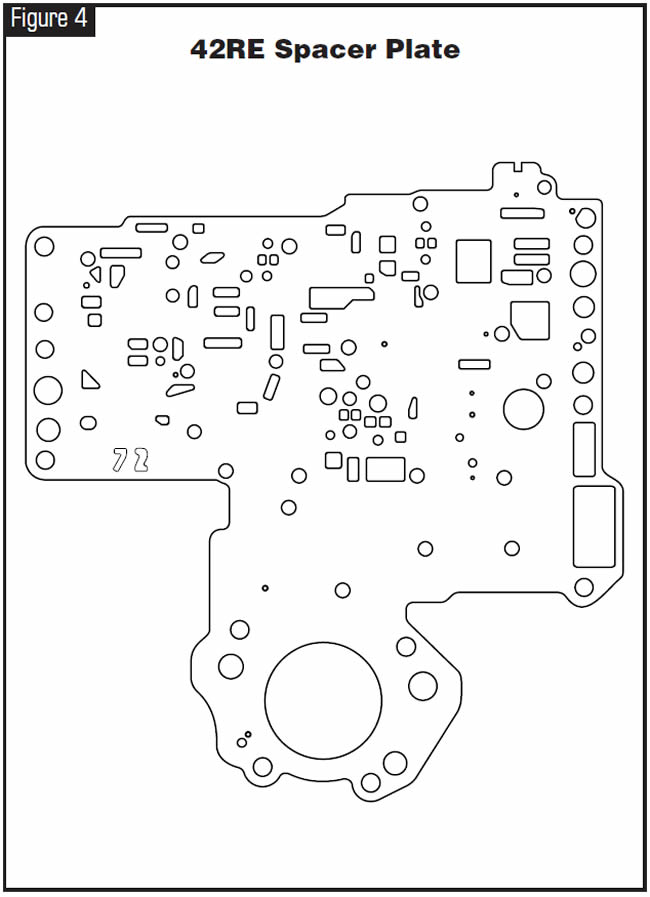
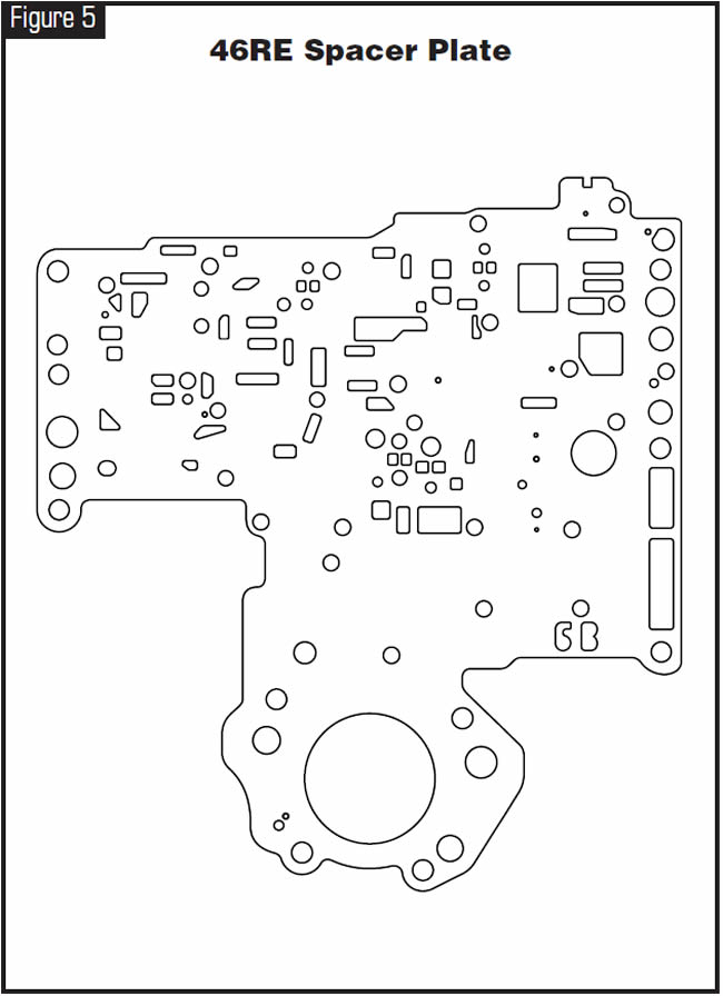
One cause may be that the No. 9 checkball has distorted the separator plate and can no longer seat correctly, allowing excessive apply pressure into the reverse-servo apply passage.
On both 42RE and 46RE, the steel No. 9 checkball should be replaced with a torlon checkball (see figure 3).

Replace the separator plate on the 42RE (see Figure 4) and the 46RE (see Figure 5).
Chrysler has issued a bulletin (21-01-00) for 1999-2000 vehicles equipped with either a 42RE or a 46RE with this complaint.

- Torlon checkball . . . . . . . . . . . . . . . . .52118261
- 42RE separator plate . . . . . . . . . . . . .52118272
- 46RE separator plate . . . . . . . . . . .4617196AB


One of these vehicles may come in with complaints of falling out of 4th gear and loss of TCC application. Code P1763 for “Governor Pressure Sensor Volts too High,” P1492 for “Battery Temperature Sensor Volts too High” and/or other sensor codes may be stored.
On diesel applications, the transmission may be stuck in 3rd gear and governor pressure may be 70 psi in Park. When you check governor-pressure-sensor voltage, the voltmeter indicates a full 5 volts! The scan tool also may show erratic engine speed.
On gasoline applications, the engine-control system may be out of “Closed Loop.” The “Battery Temp Sensor” parameter on the scan tool may indicate 350°F, and the Battery Temp Sensor volts parameter may indicate little or no voltage even when battery temperature is actually cool. Oxygen-sensor codes also may be stored.
All these complaints are caused by a bad internal computer ground. Many components share this ground, depending on model and engine application.
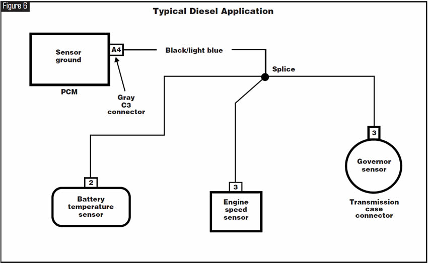
This ground is at the A4 terminal in the gray connector at the PCM. On a diesel application, the engine-speed sensor can load up with oil, which can cause the A4 ground to go bad. This results in a 5-volt condition on the governor-pressure-sensor signal wire, creating high governor pressure.
The engine-speed sensor, governor-pressure sensor and battery-temperature sensor all share this ground, along with other engine-management sensors (see Figure 6).
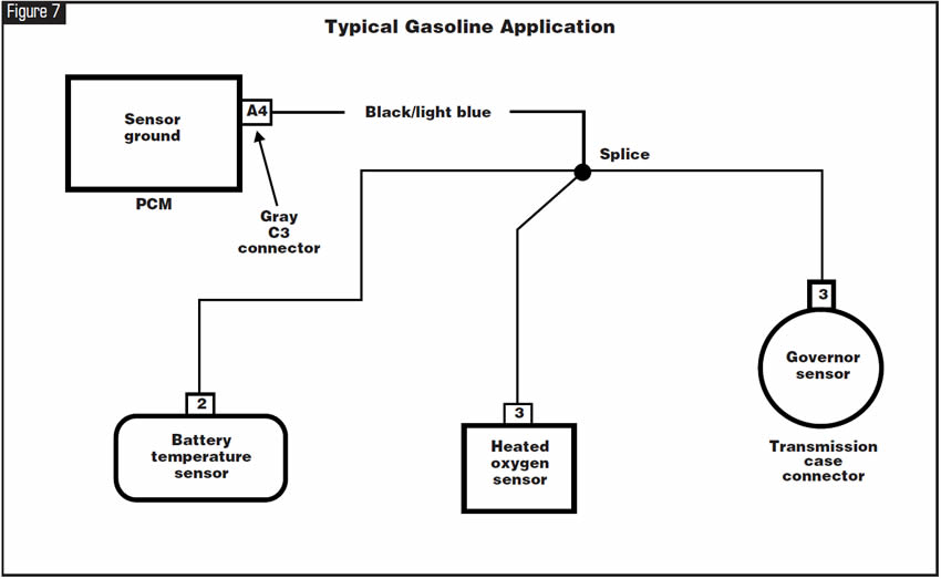
On a gasoline application the governor-pressure sensor, battery-temperature sensor and oxygen sensors share this ground, along with other engine-management sensors (see Figure 7).
The battery-temperature sensor is used to convey battery temperature to the PCM while the PCM monitors charging-system voltage to control battery charging rate. The result of this data is that charging-system voltage will be higher at colder temperatures and is reduced gradually as battery temperature rises.
The battery-temperature sensor is under the battery in the battery tray (see Figure 8).
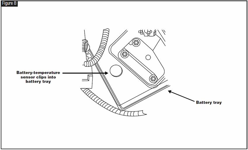
On diesel-equipped vehicles with dual batteries, the sensor is in the driver-side battery tray.
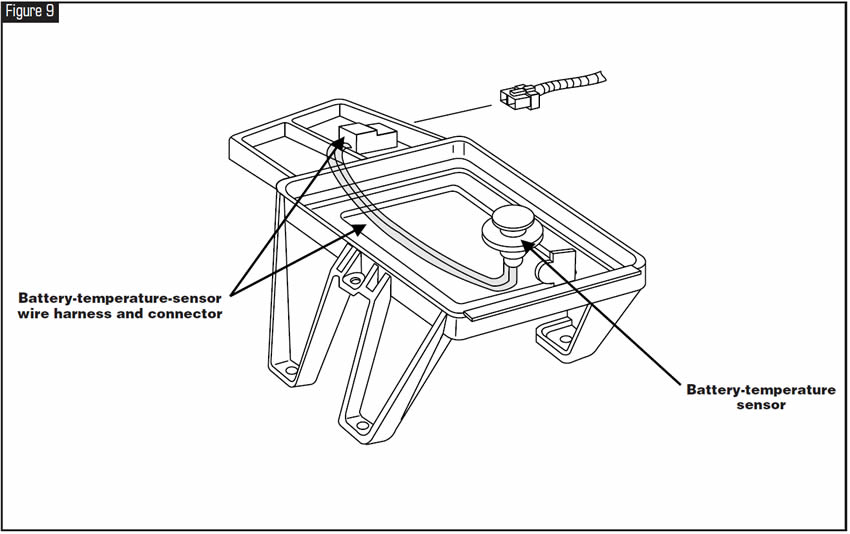
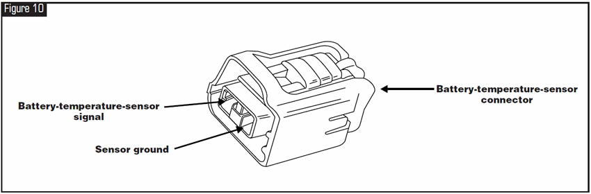
This location is enough to cause problems due to corrosion. The sensor wire harness travels under the battery tray (see Figure 9) to a two-terminal connector (see Figure 10), where the sensor resistance can be checked. Resistance values are 9,000 (9k) to 11,000 (11k) ohms at 75°F to 80°F (25°C).
The battery-temperature sensor’s temperature range is -40ºF to 389ºF (-40ºC to 199ºC). Its voltage range is 0 to 5.1.
The poorer the ground, the higher the voltage indicated will be, resulting in a high temperature reading. This sensor’s operation is opposite that of a normal thermistor.
Repair the ground or replace the sensor causing the poor ground.

February 2005 Issue
Volume 22, No. 2
- Chrysler FWD Cars & Vans:1993 & Later VSS System Diagnosis
- Chrysler 42RE/46RE: Harsh Reverse Engagement
- 1996 & Later Jeep & Dodge Trucks With RE Transmissions: Falling Out of 4th Gear, Third-Gear Starts & Loss of TCC Application