Technically Speaking
- Author: Mike Riley, Technical Editor
- Subject Matter: Dual-clutch transmissions
- Issue: Design & operation
Even though manual (standard) transmissions had evolved ever since motor vehicles were created, the greater focus of the OEMs has been toward automatics. Automatic transmissions have received more speeds, pulleys (CVT), improved converter strategy and electronics to help keep pace with an ever-changing motor vehicle. Hybrid-vehicle transmissions also tend to be automatic in nature.
But, what about blending a manual transmission and automatic transmission together?
That is exactly what was done to create the DCT. “A little bit of country and a little bit of rock and roll.” Back in the late ’80s, automated manuals were developed for some high-performance applications. An automated manual is basically a traditional stick with external electrical controls (actuators).
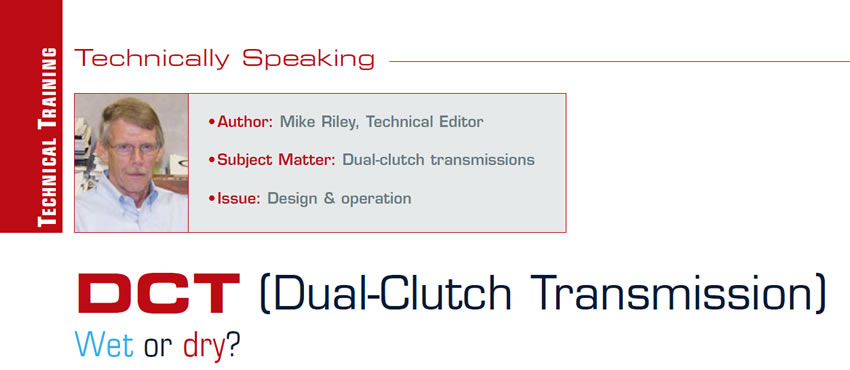
A DCT, on the other hand, is truly a manual transmission that has been automated (Figure 1). A basic difference between sticks and automatics has been in the gearing – planetary vs. external gears. Honda’s automatics are a departure from that scenario because of not using planetaries, although the rest of the transmission is automatic.
A DCT certainly resembles a manual transmission more than an automatic. The components that are colored in Figure 1 are the automatic-type items. The rest of the transmission is regular manual.
What makes a DCT unique is in the design. A DCT is actually two transmissions in one, which is what allows seamless, uninterrupted shifting. There are two inputs and two outputs with normal gears in between, resulting in two three-speeds rolled into one. It’s all about odd and even. The solid input shaft is driven by the large-diameter clutches, which control first, third and fifth gears. The hollow input shaft is driven by the small-diameter clutches, which control second, fourth and sixth gears.
While the vehicle is being driven in first gear, the computer selects and engages second gear; however, the actual apply does not happen until the large and small clutch packs reverse their apply and release status. Shifting continues in this manner up to sixth gear and back down to first. The driver never feels the synchronizer.
The DCT in Figure 1 is a “wet”-type DCT, code 02E, which was developed by BorgWarner and used by VW under the name DSG (Direct Shift Gearbox). All the components are internal and the unit is controlled like a regular automatic.

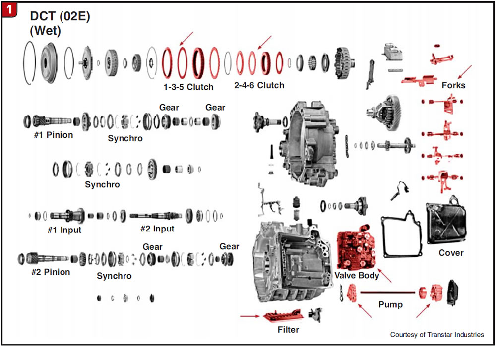
The dual-clutch assembly is a unique design and is used in place of a torque converter or traditional standard-transmission clutch. It provides not only the initial launch of the vehicle but also all upshifts and downshifts. It is a compact clutch assembly that can be partially disassembled (Figure 2).
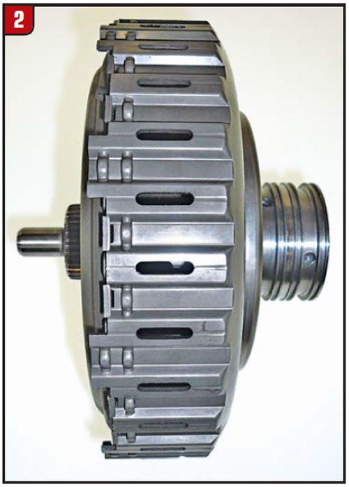
The clutch plates and small-diameter piston can be replaced, whereas the large-diameter piston cannot be because of the welded assembly method chosen by BorgWarner (Figure 3).
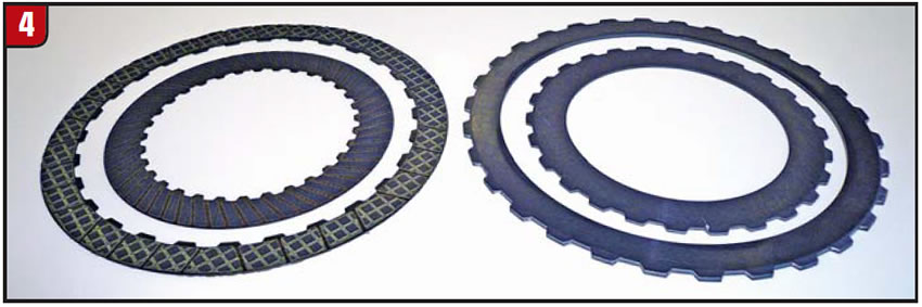
The frictions and steels are normal automatic-looking plates and function the same way as well (Figure 4).
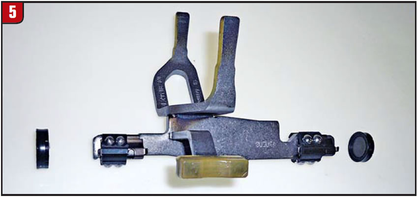
With the dual clutch responsible for launch and gear apply, what about the shifting of the transmission? That falls to the synchronizers, just like in a manual transmission, but with one difference: The driver doesn’t do it. The shift forks are moved hydraulically by using small molded-rubber pistons at each end of the shift fork (Figure 5). A normal gear-type pump provides the line pressure. The filter is also a regular-type AT filter; however, replacement requires disassembly.
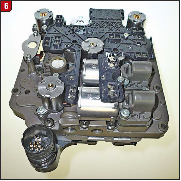
None of this would be possible without proper controls, meaning a valve body. The 02E has a valve body to rival anything on the street (Figure 6). It has a slew of solenoids, sensors and valves. In addition, the valve body is mechatronic, which means that it includes the TCM.
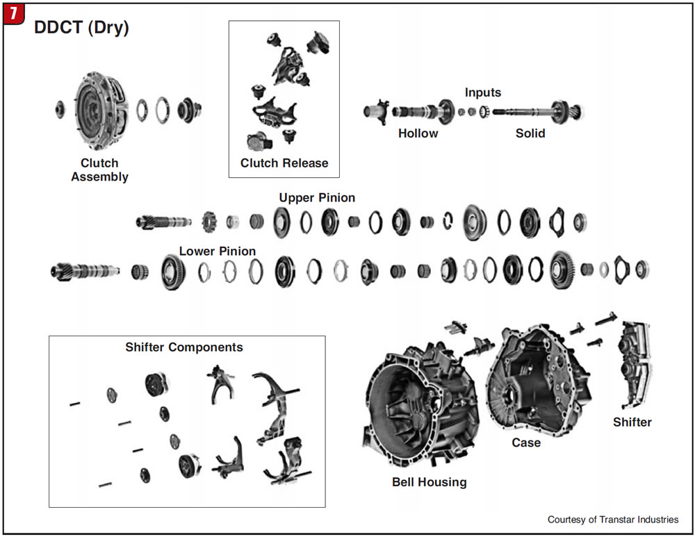
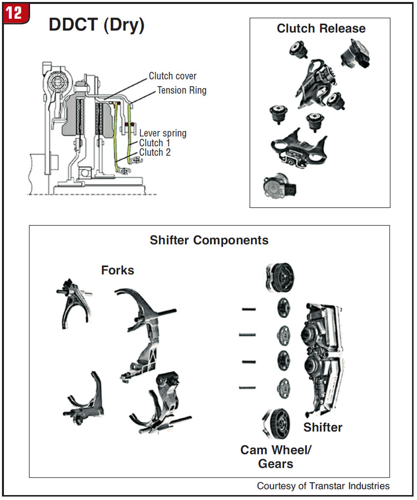
Another type of transmission is the “dry” DCT or DDCT (Dry Dual Clutch Transmission). Although controls of the DDCT are nothing like those of the DCT, internally both models function the same relating to gears, shafts, synchros etc. (Figure 7).
As with the wet DCT, the DDCT also uses a dual-clutch assembly, although they are not the same. The DCT clutch assembly is internal and hydraulic, whereas the DDCT clutch assembly is external like a regular standard-transmission clutch. The DDCT clutch is also two clutches in one, with each disc driving the solid and hollow input shafts.
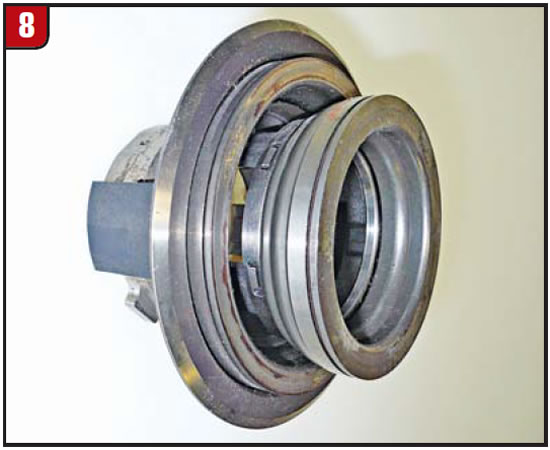
What operates the clutch assembly is the throw-out bearing – actually “bearings,” which are two rolled into one (Figure 8).
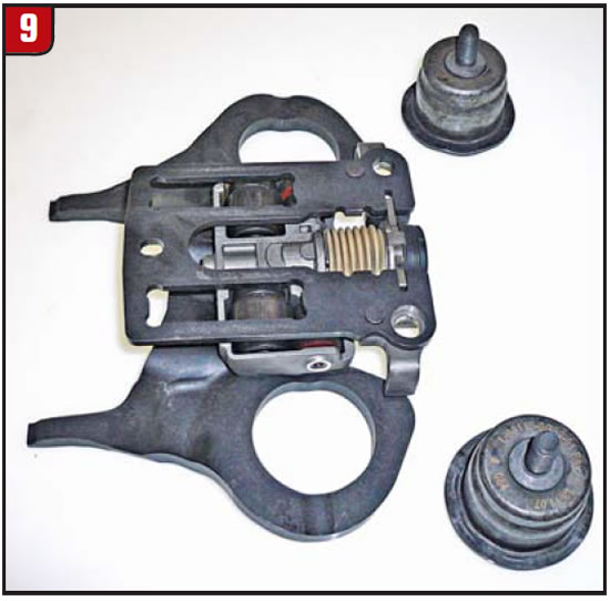
There are also two gear-driven clutch forks that operate each throw-out bearing (Figure 9).
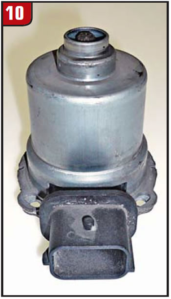
The forks are moved by two small electric motors that have gears at the end (Figure 10). The motors are controlled by the computer and must provide the exact rate of apply and release of the clutch to avoid countless problems. The clutch assembly was designed and produced by LuK.
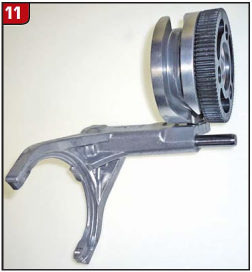
Shifting the transmission is equally complex. Unlike the DCT shift forks, which are applied hydraulically, the DDCT uses a computer-operated shifter motor, two sets of idler gears and two cam wheels to move the various shift forks. The cam wheels have ramps cut into them to engage the fork inserts (Figure 11), which ultimately will move left to right.
Although the DDCT is more in sync with a regular manual transmission than the DCT, it is certainly a step above the norm. To date, dry DCTs are primarily used for smaller vehicles, but that can change at any time.
The components in Figure 12 represent what is needed to operate a DDCT through computer strategy. The question is, are these additional controls and designs worth the effort beyond what has been done previously?
In any event, the next time that a vehicle shows up for repair and has a DCT, remember to check “is it wet or is it dry?”


