


Ford needed to address specific shift and capacity concerns on the 6R60/6R80 family of transmissions relating to the low/reverse D clutch.

The 6R60/80 is a clutch-to-clutch shifting type of transmission (synchronous shift), which means that timing is crucial between the releasing clutch and applying clutch. Incorrect timing of the two clutches can result in either overlap (bind-up) or flare-up (cut-loose), reducing the life of the clutch as well as causing drivability issues.

The Ford 6R60/75/80 models were based on the ZF 6HP26 transmission released in 2002. The transmission has a mechatronic valve body, which means that the TCM is integral with the valve body. (Note: Beginning in 2010 certain Ford models are no longer using mechatronic. The TCM is external.)
The GM 6L50/80/90 models were also based on the ZF design with a few differences; e.g., vane-type pump, forward-/direct-clutch configuration etc. One big GM departure was that the models all use a low sprag OWC (one-way clutch).
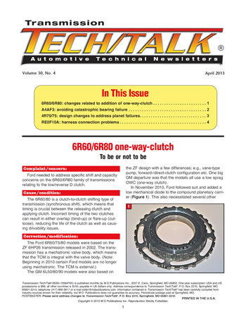
In November 2010, Ford followed suit and added a low mechanical diode to the compound planetary carrier (Figure 1). This also necessitated several other component changes, not only to physically accommodate the OWC but also to address the way that the low-reverse clutch will apply.
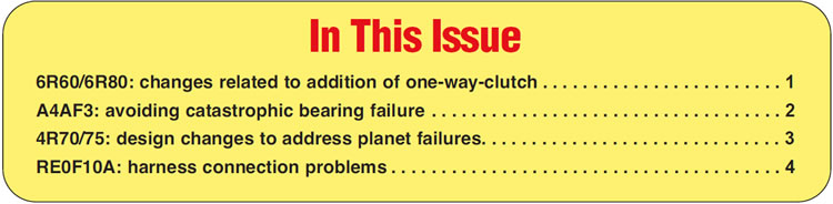
Pre-OWC models apply the low-reverse clutch similar to how the 400/4L80-E transmissions apply the forward/direct clutches, in that the piston has two separate chambers to control the rate/timing of the clutch. Models with the OWC have one apply cavity, like a regular piston. This means that the valve body has been redesigned accordingly and would not be interchangeable with previous models (Figure 2).
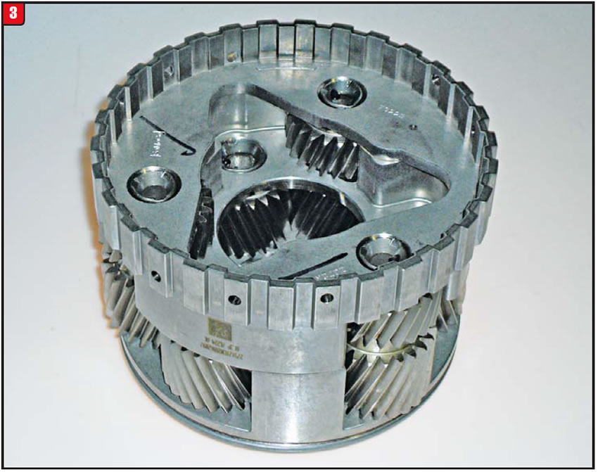
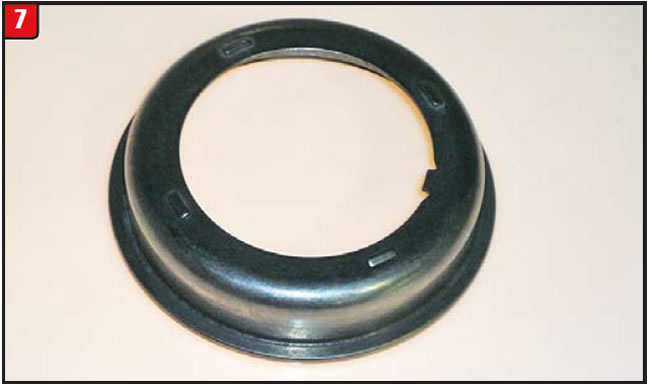
The rear (compound) planetary was modified slightly to mesh with the outer race of the diode. The inner race, which is the main support, will spline to the case (Figure 3).
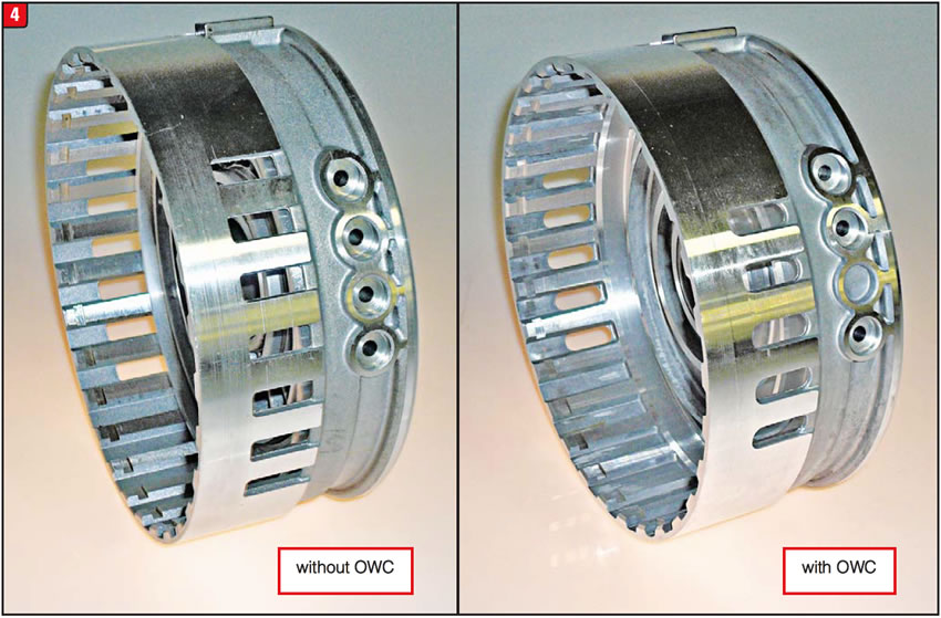
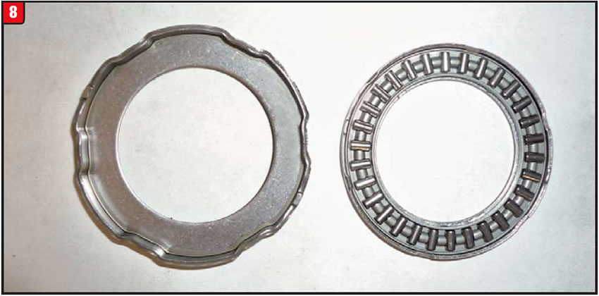
Other components include the center support, which doubles as the C/D (intermediate/low-reverse) clutch/piston housing. The first thing to note about the center support is the missing apply-oil hole.
The missing hole is one of the two that apply the low-reverse clutch (Figure 4). The back side of the support is the cavity into which the low-reverse piston fits. The main difference is that the pre-OWC design has three piston seals – inner, outer and center – whereas the new design has just two seals, the inner and outer. The piston return-spring snap-ring groove was also repositioned to accommodate a new spring and retainer.
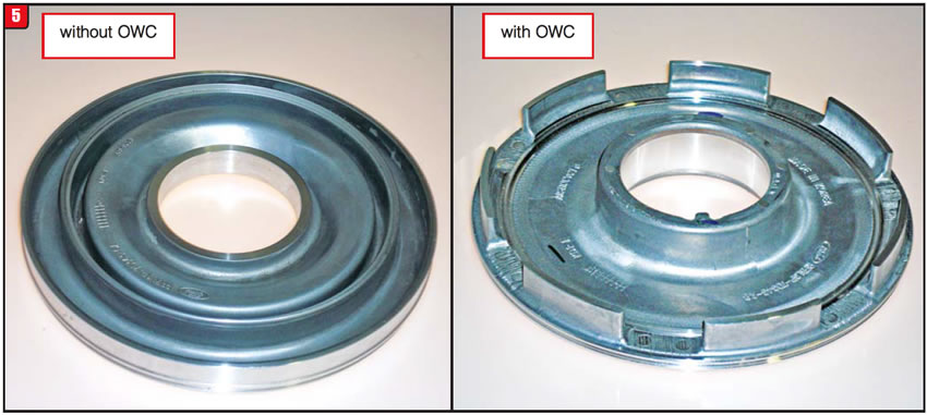
The low-reverse piston was changed to eliminate the center-seal area. The apply surface is basically flat. In addition, there are now lugs on the clutch side of the piston that protrude through holes in the OWC (Figure 5). The lugs are what contact and apply the low-reverse clutch.
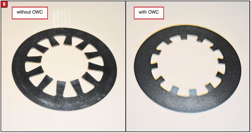
Because of the redesigned piston, the piston return spring was also changed. The overall diameter is different and the pressure angle was changed. The result was a deeper pocket to accommodate the OWC assembly (Figure 6).
Last, a steel cupped retainer (Figure 7) was added to enable using the lower-angle piston return spring. Previous models merely had the snap ring retain the return spring.
The remaining questions are will this upgrade accomplish the goal, what will it take to outfit previous models with the new OWC, and will it be worth doing?To be or not to be, that is the question!


The 2000-up Hyundai A4AF3 series of transmissions (six solenoids) may experience a bearing noise that could result in complete bearing failure. Although the bearing/race may appear to be sound during rebuilding, failure could occur later on.
The original design of the bearing and race between the end-clutch hub and output-gear nut tended to be deficient and could break apart at any time. When the end clutch applies, hydraulic pressure exerts a force on the clutch drum, moving it forward toward the output gear, which loads the bearing and race.
In mid-2005 Hyundai made a modification to the cupped bearing race on the output-gear nut. The thickness was increased by about 0.030 inch to limit the possibility of breaking (Figure 8). The overall thickness of the first-design set (bearing/race and cupped race) is 0.160 inch. The second-design set is 0.190 inch thick.
Both first and second designs are still available under OE part numbers 45525-22800 (2000-2005) and 45525-22810 (2005-up). It is possible to update the early models to the thicker second-design bearing set and improve durability. Itʼs all about clearance.
The end-clutch drumʼs endplay tends to be excessive no matter what the year, and if the clearance is sufficient, replace the thin set with the thick set.
Place the output gear with the support and nut into the case. Then set the end-clutch assembly, hub and thick bearing set onto the output gear. Last, install the end cover and tighten with a couple of bolts. Look through the sensor hole in the end cover and use a screwdriver to move the end-clutch drum. If thereʼs clearance, itʼs a go, and forget about the time bomb!


A 4R70W-type transmission exhibits a grinding/growling noise at various speeds, and the ultimate result is catastrophic failure. In addition, a potentially bad bearing is not detected during the rebuilding of a unit for other causes, such as clutch failure. Erratic shifting and certain trouble codes can also occur.
Certain forward-sun-gear to planetary-carrier thrust bearings tend to fail prematurely. Bearing design and sources have changed over the years. However, the bearings used in models beginning in 2008 are of special concern, according to Ford.
Since 1993, the 4R70W has undergone several changes and upgrades due to production, capacity and supplier concerns. Changes in electrical requirements also resulted in component upgrades. Mismatching certain components will cause stack-up issues; mismatching other components can cause shifting or trouble-code problems.
The following are some of the changes to be aware of:
When the 4R70W was launched in 1993, the key distinction from the AODE was the planetary components. The planet and both sun-gear tooth counts were different; hence, the name 4R70W (wide ratio).
Even before the 4R70W hit the streets, changes had occurred to the “captured” planet bearing used on AOD/AODE planets. The captured bearing on the 4R70W planet was different from the other bearings as well.
Although subtle changes took place from time to time, a significant change occurred in mid-2003 to the 4R70W. The bearing between the reverse sun gear/shell and the forward sun gear was increased in thickness by about 0.035 inch. To accommodate the thicker bearing, modifications were made to the sun gears. The forward sun gearʼs width was reduced only slightly, whereas the reverse sun gear/shell was cut by almost 0.030 inch.
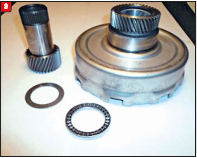
At that point, Ford discontinued the previous-design components and released an update package to retro-fit to 1993 (Figure 9). The components must be used as a set or else stack-up issues will arise.
The upgrade pace really picked up in 2004 when Ford released three more models, the 4R75W, 4R70E and 4R75E. All four models got a pump facelift with redesigned sealing rings and a bonded intermediate piston.
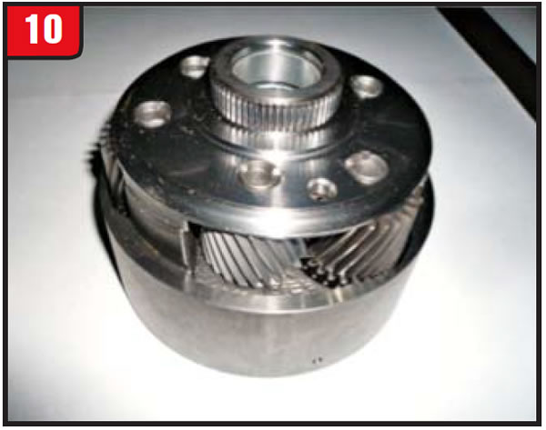
What distinguished the models was more toward the back of the transmission. The primary difference between the 70 and 75 series had to do with the planetary. The 70-series models still used a riveted planet, whereas the 75-series models got a welded planet (Figure 10).
But then again, what did it mean, since Ford ultimately discontinued the riveted planet and now produces only the welded one. The stack-up of both designs is the same and both are interchangeable, although the captured bearing could be different.
The series change that was more significant had to do with the W and E models. To accommodate the center speed sensor used on the 4R70E/75E units, a special non-magnetic sun-gear shell was used. Initially the shell was riveted to the sun gear but was switched to a welded design later on, just like previous shells. Non-magnetic shells must be used on E models but can be used on W models as well.
To date, the sun-gear/bearing package produced in mid-2003 is for only W models because the shell is a magnetic type. The non-magnetic shell must be used on E models so that the sensor can read through to the input drum, which was also modified for E models.
Last, 2004-up ring gears no longer have holes for the rear sensor to read but rather use the park lugs instead. The rear sensor was made shorter as well.
More recently, supplier changes have apparently resulted in an inordinate number of planet-bearing failures, and Ford is addressing this issue with a complete planetary package.
A couple of different packages are available depending on application. However, the main components are the same. One such package number is AL3Z-7A398-C. The packages include the reverse and forward sun gears, planet, direct-clutch drum and over-haul-kit components. All the items are available separately and are carried by many distributors.
When rebuilding this family of transmissions, be sure to inspect all bearings closely, especially the captured planet bearing. Above all, know the changes, prevent the grief.

A 2009 Jeep Patriot with a continuously variable transmission experiences a variety of drivability concerns and sets several different trouble codes; e.g., P0700, P0842, P0847, P0963, P0967, P1280, P1729, P2017, P2770.
As with all computer-controlled transmissions, the RE0F10A CVT uses an external harness, which runs from the computer to the transmission-case electrical connector. Because of time, the elements, vibration and location of the case connector, inconsistent terminal contact may occur. Corrosion of the wiring is also possible.
Before replacing the computer or dropping the pan to replace solenoids, try to erase all codes and drive the vehicle again to see whether the same codes return. Certain codes may not. If the condition is erratic, the harness may be the issue. Clear all codes again and with the vehicle on the rack, try to wiggle the harness and wires. If any codes return, replace the harness/plug.
Unlike many vehicles that require an entire harness, stretching out for miles, the Caliper/Compass/Patriot vehicle family has a repair harness and connector available (part # 68086740AA).
Note: Always verify part number and application information.
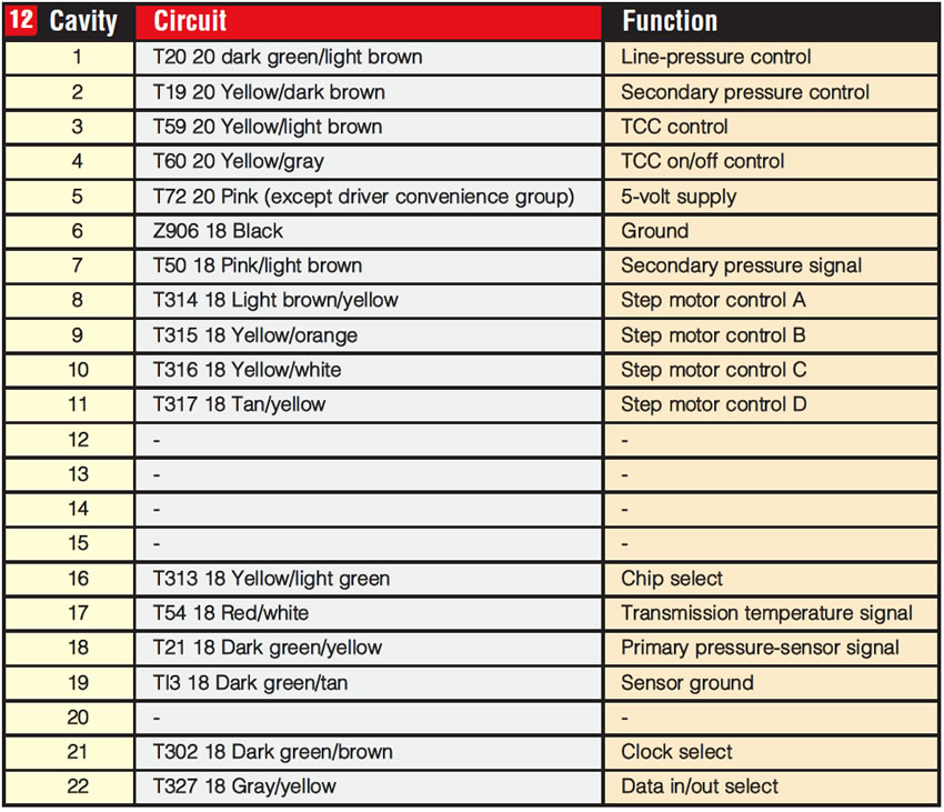
Although the wires are color coded, it will still be somewhat of a chore to replace because of the number of wires, 17 in total (Figure 11). As with splicing together any repair harness, use caution to ensure good connections and use heat-shrink tubes as well as stagger the cuts.
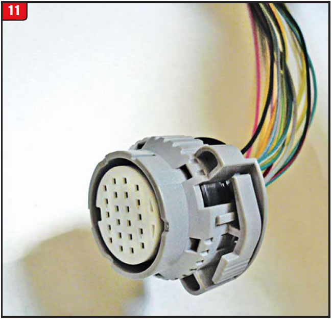
If the color of certain wires is not apparent, refer to Figure 12 for plug-cavity to wire-color position.

April 2013 Issue
Volume 30, No. 4
- 6R60/6R80: changes related to addition of one-way-clutch
- A4AF3: avoiding catastrophic bearing failure
- 4R70/75: design changes to address planet failures
- RE0F10A: harness connection problems


