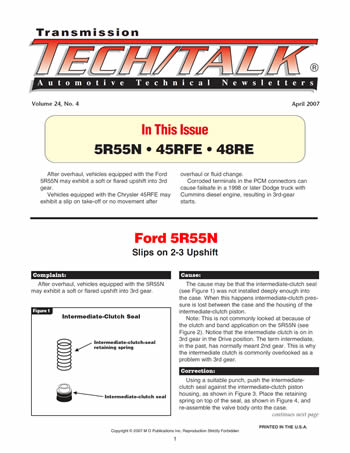


Issue Summary:
- After overhaul, vehicles equipped with the Ford 5R55N may exhibit a soft or flared upshift into 3rd gear.
- Vehicles equipped with the Chrysler 45RFE may exhibit a slip on take-off or no movement after overhaul or fluid change.
- Corroded terminals in the PCM connectors can cause failsafe in a 1998 or later Dodge truck with Cummins diesel engine, resulting in 3rd-gear starts.


After overhaul, vehicles equipped with the 5R55N may exhibit a soft or flared upshift into 3rd gear.

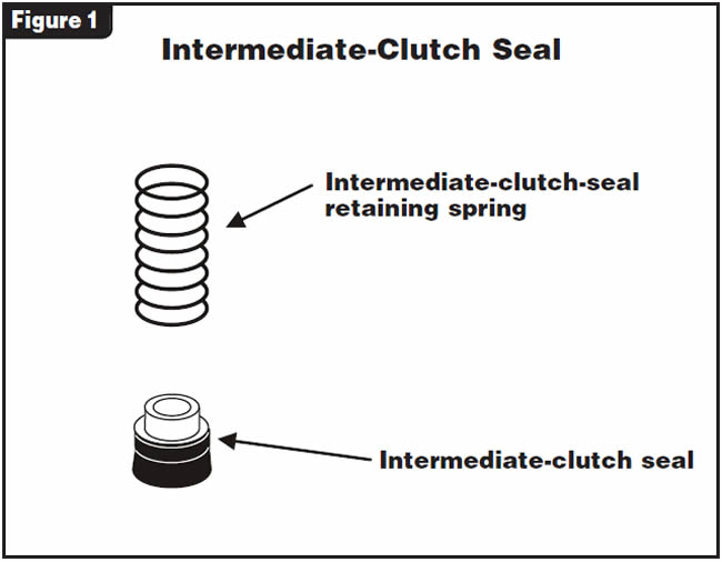
The cause may be that the intermediate-clutch seal (see Figure 1) was not installed deeply enough into the case. When this happens intermediate-clutch pressure is lost between the case and the housing of the intermediate-clutch piston.
Note: This is not commonly looked at because of the clutch and band application on the 5R55N (see Figure 2). Notice that the intermediate clutch is on in 3rd gear in the Drive position. The term intermediate, in the past, has normally meant 2nd gear. This is why the intermediate clutch is commonly overlooked as a problem with 3rd gear.

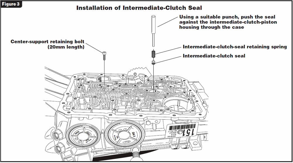
Using a suitable punch, push the intermediate-clutch seal against the intermediate-clutch piston housing, as shown in Figure 3.
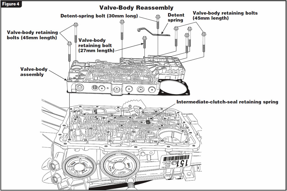
Place the retaining spring on top of the seal, as shown in Figure 4, and re-assemble the valve body onto the case.


Vehicles equipped with the 45RFE may exhibit a slip on take-off or no movement after overhaul or fluid change.
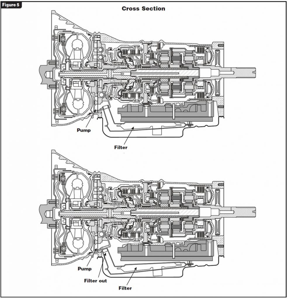
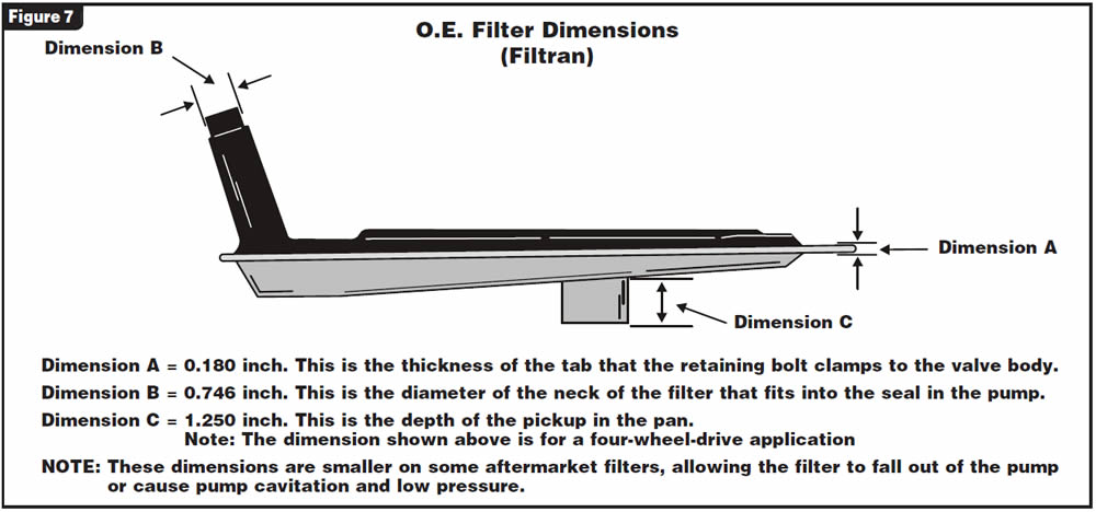
The cause may be that an aftermarket primary oil filter was installed into the transmission and the neck of the filter is too narrow, allowing the filter to fall out of the pump and cause fluid aeration and/or no pump suction, as shown in the cross-section in Figure 5.
Locate the primary oil filter (see Figure 6).
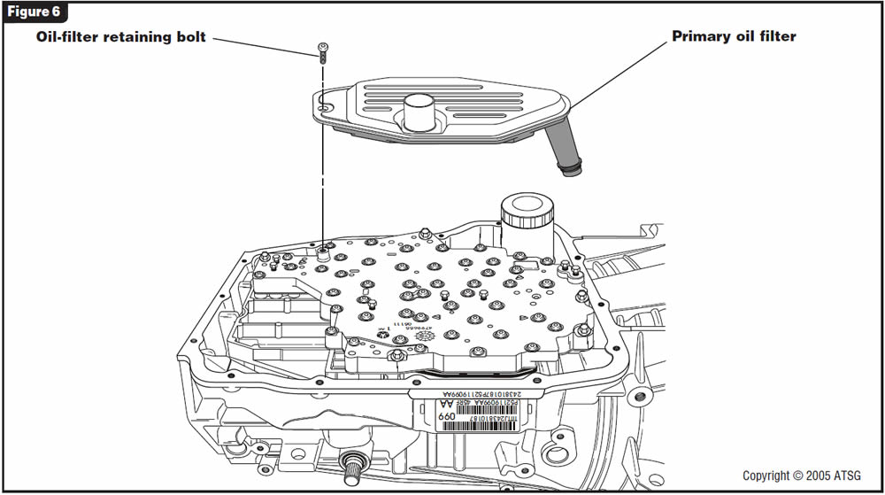
Remove it from the pump and verify that the dimensions of the filter are the same as those shown in Figure 7. Replace as necessary.


The vehicle that spawned this bulletin was a 2003 Dodge truck with a 5.9-liter diesel engine and 48RE transmission. The truck came into the shop with complaints of taking off in 3rd gear and that only the park and neutral gear-select indicator lamps would illuminate. The scan tool could retrieve code P0700, “Transmission Fault Present,” from the Cummins ECM but could not receive PCM communication for transmission information.
Verification that the PCM was not grounding the transmission-control relay was made, indicating that the system was in failsafe. Power and grounds at the PCM were checked and deemed good.
During the diagnostic procedure, a voltmeter was connected to terminal 30 at the C2 (white) connector to monitor the PCM-controlled ground for the transmission-control relay. While connected to terminal 30, the wire lead was removed from the meter and tapped to ground. When the meter lead was plugged back into the meter, the meter indicated 0.1 volt, which meant the PCM was grounding the circuit and the relay should be energized. A road test confirmed this and the transmission performed perfectly – until the ignition was cycled. The third-gear start along with the other complaints also returned at this time.
The process of tapping the meter lead to ground again also restored correct operation of the transmission. Replacement of the PCM did not cure the problem.
Sometimes when you’re checking a power or ground circuit, just back-probing the terminal in question is not sufficient; this is one of those times. When the C1 (black) connector was disconnected and terminal 22 was checked, the face side of the terminal had only 1.8 volts. The back side of the terminal had 12.9 volts. This circuit provides key-on power from the 20-amp #19 fuse in the integrated power module in the engine bay, on the driver side in front of the PCM.
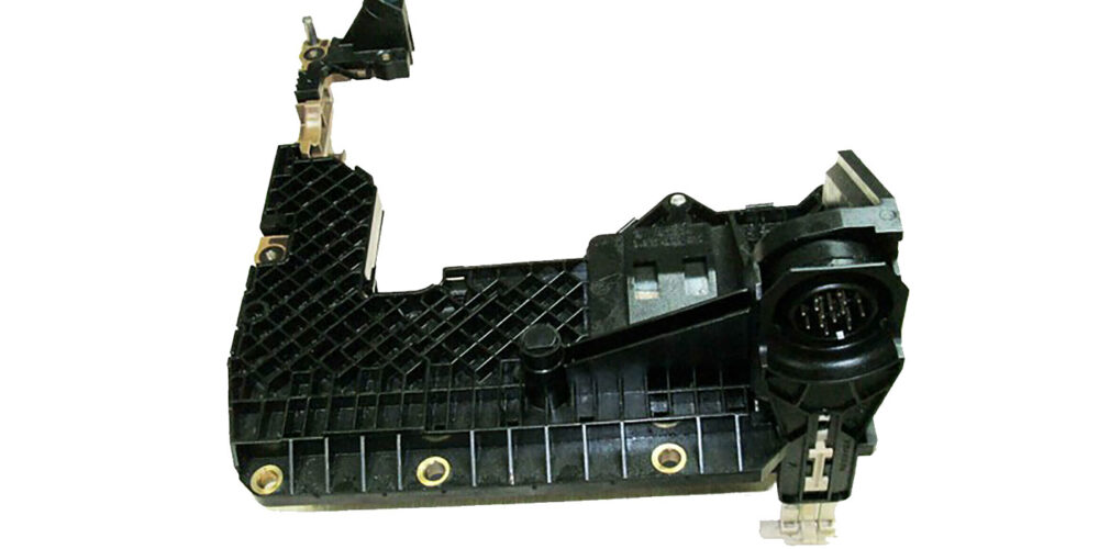
After the connector was pulled apart, the cause of these complaints was obvious. The terminal end (refer to Figure 8) was severely corroded.
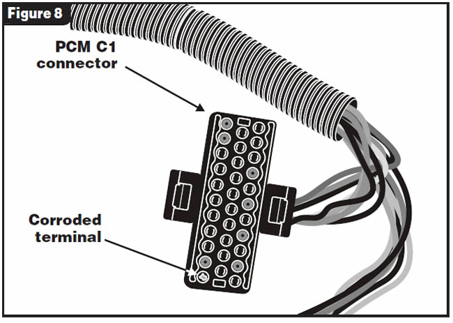
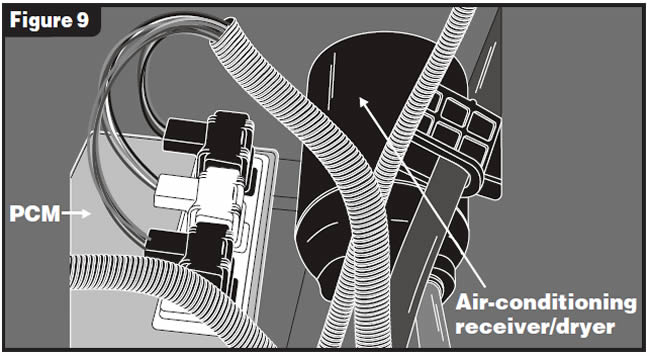
Figure 9 shows the reason for the corrosion: The PCM connectors are next to the air-conditioning receiver/dryer. The condensation created by the receiver/dryer compromised the C1 connector, which led to the severe corrosion.
Replace the damaged terminals with wire-end repair kits (refer to Figure 10), then protect them from the A/C condensate.
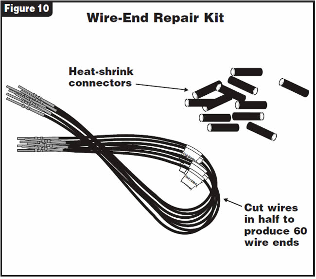

- Connector A (32-terminal black C1 connector) . . . . . . . . .56017957
- Connector B (32-terminal white C2 connector) . . . . . . . . .56018614
- Connector C (32-terminal gray C3 connector) . . . . . . . . . .6018615
- 20 wires w/terminal ends (total of 40) w/40 pieces of heat-shrink tubes . . . . . . . . .04882087
- Connector cover . . . . . . . . . . . . . . . . . . . . . .56018606
- Connector plug . . . . . . . . . . . . . . . . . . . . . . .56038347
Service Procedure:
- Record the memorized preset radio stations
- Disconnect the battery or batteries on 5.9-liter diesel Cummins and isolate the cable ends.
- Unplug the damaged connector from the PCM
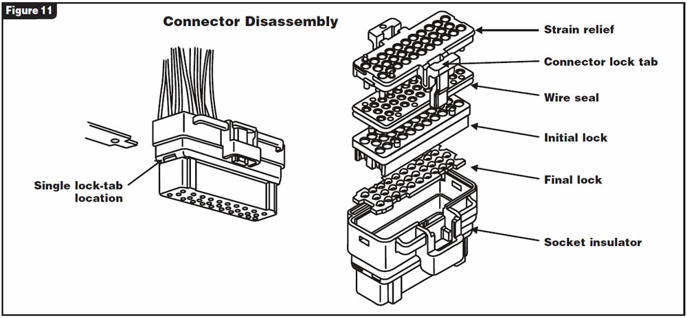
- Locate and inspect the connector lock tab and insulator for damage (see Figure 11). If it is damaged, the entire connector will need to be replaced.
- Write down each wire color and its appropriate cavity location within the connector before disassembling the connector.
- Next, pull on the wires individually. If they come out the connector will need to be disassembled to inspect the initial and final locks (see Figure 11).
- To disassemble the connector, push in on the single locking tab (refer to Figure 11).
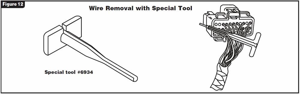
- Use Chrysler’s special tool 6934 or one similar, inserting the tool into the back of the insulator cavity alongside each wire, removing them from the connector assembly one at a time as shown in Figure 12.
- With all the wires removed from the connector, inspect the entire connector assembly (refer to Figure 11). If any of the parts are damaged, replace the connector assembly.
- While the wires are out of the connector, inspect each terminal end for damage or corrosion. Place each terminal end onto the mating pin in the PCM and check for drag. If any connections are loose, replace the wire.
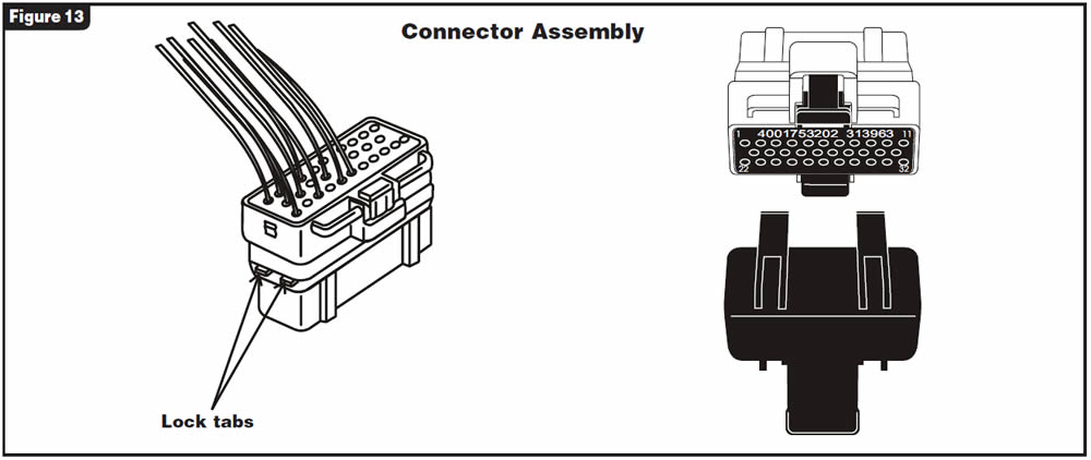
- Using the notations of wire color and location made in step 5, carefully assemble the new and/or repaired connector assembly. When all the wires are in place, push the two locking tabs into place to secure the wire terminals in the connector assembly (see Figure 13).
- Cross your fingers, attach the battery cable or cables, reset the radio station and hope that all your codes do not return.

April 2007 Issue
Volume 24, No. 4
- Ford 5R55N: Slips on 2-3 Upshift
- Chrysler 45RFE: Slips on Take-Off or Doesn’t Move
- 1998 & Later Dodge Diesel Trucks: Third-Gear Failsafe