

Issue Summary:
- Incorrect interchange of pump covers and input shafts in 1997-2006 GM vehicles with 4L60/65/70-E transmissions can cause a variety of problems.
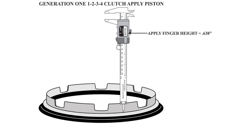
- GM vehicles equipped with the 6L80 transmission may exhibit a complaint of a slip on takeoff in the forward ranges, typically in first gear, and code P2723 or P2728 may be present.
- On Freightliner/Dodge Sprinter vans with roof-mounted electric ventilation fans, the transmission may go into limp mode when the fans turn on.


Diagnostic trouble codes P0716 and P0717 may be stored; no torque-converter fill; burnt frictions in the input drum; planetary-gear-set destruction; or TCC-application problems.

Incorrect interchange of pump covers and input shafts.

At the start of production for the 2006 model year an input-speed sensor (ISS) was added to some 4L60/65/70-E transmissions. This necessitated changes to the pump cover and input shaft.
The ISS signal is an input to the control module (PCM or TCM) that will be used to better monitor and control line pressure, shift patterns, torque-converter-clutch slip speed and gear ratios. This component will allow the 4L60/65/70-E transmissions to enable use of computer instructions (algorithm) related to shift energy and abuse-torque management and provide much-improved diagnostic capabilities.
The new turbine input-shaft-speed sensor was gradually phased into production, and certain design-level criteria had to be followed. The following information is intended to provide a general outline of the stages involved to implement the use of the ISS.
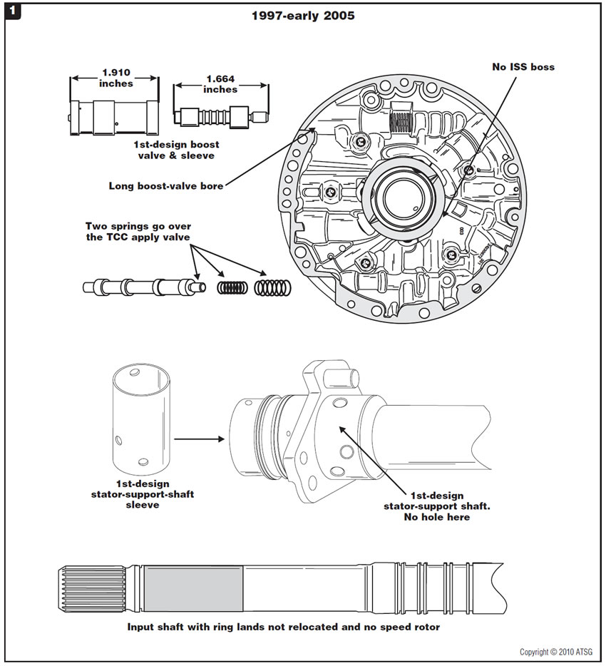
- In model years 1997 to early 2005, the 4L60-E series transmissions used a pump cover with no provisions for an ISS, the input-shaft sealing-ring grooves had not changed and there was no speed-sensor rotor. The pump cover used the first-design internal stator-shaft sleeve and the first-design boost valve, which is 1.664 inches long with a boost-valve sleeve 1.910 inches long, as well as two springs that went on the TCC apply valve (Figure 1).
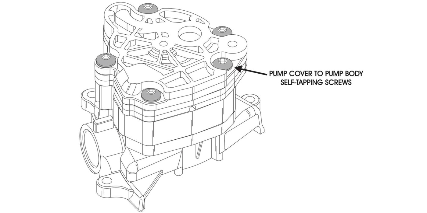
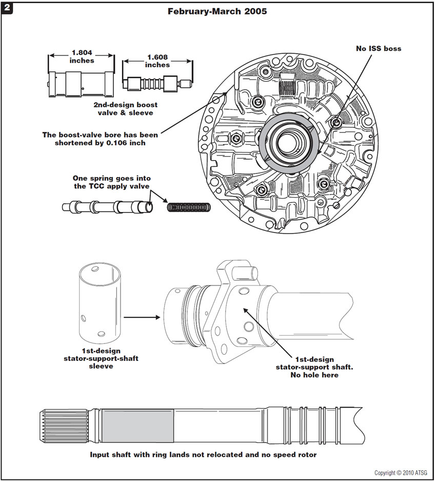
- Effective Feb. 1, 2005, the oil-pump cover now uses a new-design TCC valve with a single spring (Figure 2).
- Effective March 7, 2005, the oil-pump cover now uses a more-compact boost valve and sleeve. The snap-ring groove for the boost-valve sleeve is now 2.57 inches from the bottom of the bore, compared with 2.68 inches for the previous design. The bore length for the boost-valve sleeve and snap ring has been reduced by about 0.110 inch (Figure 2).
- After July 16, 2005, the pump-cover casting was modified to situate the ISS connector. This modification removed metal directly below the PR valve and boost-sleeve bore and extended a cast wall inward. The internal TCC-release passage also was modified at this time. The ISS mounting holes are not yet machined into the oil-pump cover (Figure 3).
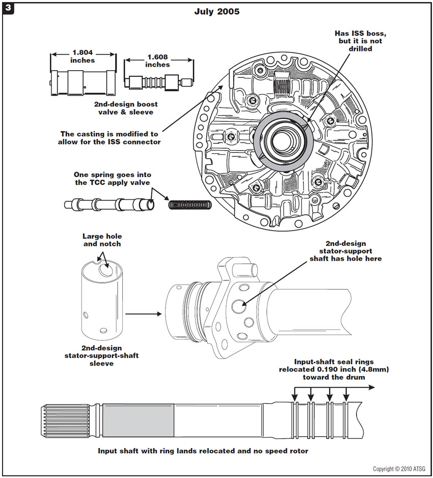
Changes to the oil-pump cover also affected the stator shaft and stator-shaft sleeve so as to relocate with oil passages within the oil-pump cover.
At the same time, the grooves for the turbine-shaft oil-seal rings were moved inboard toward the rear of the unit about 0.190 inch to produce an area with which to manufacture 15 rotor teeth (Figure 3).
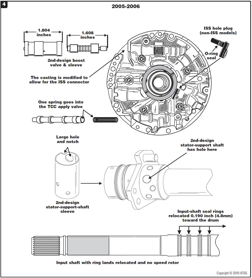
(4) Some late-2005 and early-2006 pre-ISS models may still not have the ISS mounting holes machined into the cover. This will be evident as a smooth, unmachined surface without the ISS mounting holes. For non-ISS models, an ISS hole plug will be used in place of the ISS assembly (Figure 4).
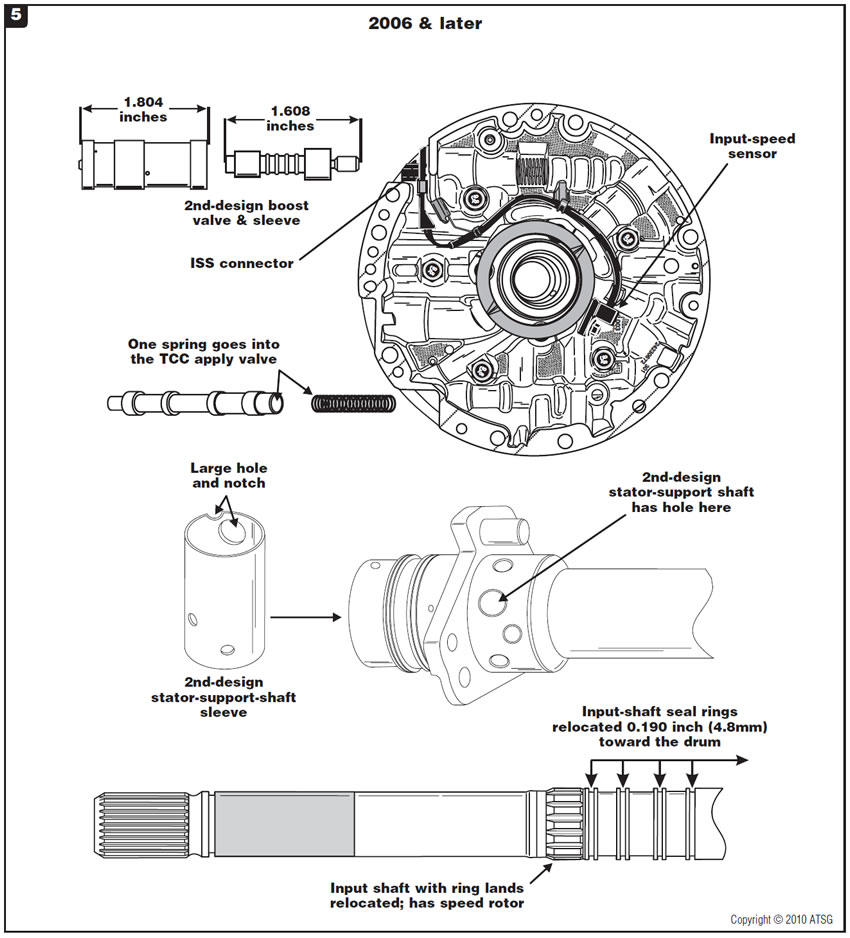
As ISS models were introduced, later in the 2006 model year, the machining took place and the ISS was added (Figure 5). The presence of the ISS also necessitated a new internal wire harness to accommodate the ISS and software changes to the PCM to provide code capability for ISS malfunctions.
On non-ISS models that have a functional ISS hole in the pump cover, the rubber plug with an O-ring seal must be installed. Failure to do so will result in no converter charge and the vehicle will not move.
If an input shaft without the speed rotor is used and the pump cover has an ISS, code P0716 or P0717 will be stored, which could cause TCC slip and gear-ratio-calculation errors.
If the pump cover and input shaft are mismatched, severe friction and geartrain damage will occur in a short time.
Note: When parts are modified and are phased into production to prepare for the change, it is imperative that the correct replacement parts be used. The parts you may find in a particular transmission may not coincide exactly with the published phase-in time periods. The dates provided are for general purposes to help make identification of parts easier.


Vehicles equipped with the 6L80 transmission may exhibit a complaint of a slip on takeoff in the forward ranges, typically in first gear. This complaint may be accompanied by diagnostic trouble code P2723 Clutch Pressure Control Solenoid 5 (1-2 3-4) “Stuck Off” or P2728 Clutch Pressure Control Solenoid 5 (1-2 3-4) “Performance.”
The cause may be a shrunken or missing No. 1 nylon checkball. Refer to Figure 6 for the location of the checkball in the upper valve-body assembly. The No. 1 checkball is in the upper valve body (Figure 6). When the transmission is operating in drive 1st, 2nd, 3rd, 4th, 5th or 6th gear, drive 1-6 fluid seats the checkball against the drive braking passage and enters the 2-6 clutch/1-2-3-4 clutch feed circuit to apply the 1-2-3-4 clutch. When the checkball shrinks or disintegrates, 1-2-3-4 clutch pressure will pass through the ball seat to an exhaust provided by clutch select valve 2. Figure 6 provides a partial schematic.
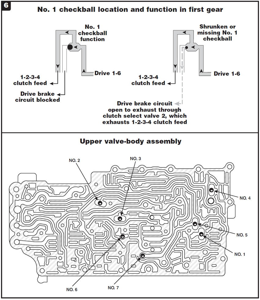
Note: The DTCs listed here are performance codes related to the solenoid that controls application of the 1-2-3-4 clutch. A missing checkball can cause these codes to set. Do not assume that the TCM/solenoid assembly is faulty; it could be a simple checkball!
Replace the nylon checkballs with 1/4-inch Torlon checkballs available in most aftermarket Torqueflite kits, including 42-48RE. These checkballs are made from more-durable material.

- Torlon 1⁄4-inch checkball (Chrysler part number) . 52118261


The vehicle comes into the shop with the transmission in “Limp Mode.” No codes are stored in the TCM memory, but there may be a “System Under Voltage” message in the driver information center.
On Sprinters equipped with electric ventilation fans mounted in the roof, the fans are wired into the TCM power-supply circuit (Figure 7).
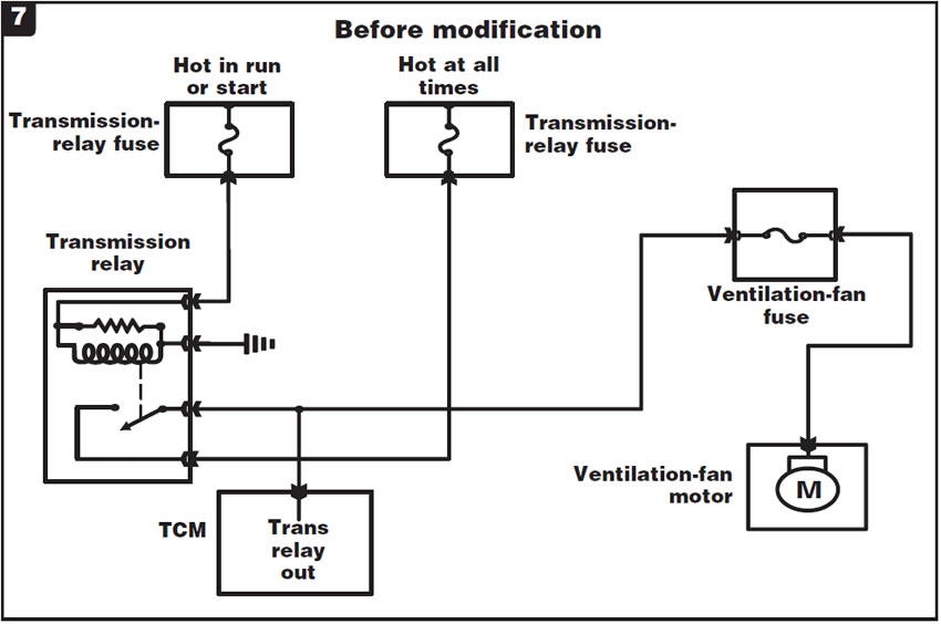
The fans draw too much current for one relay when they turn on. This causes a voltage drop across the transmission-control relay, which causes a voltage drop to the transmission and results in a “Limp In” condition. The key to this problem is that it goes to limp mode only when the fans come on.
A relay and wiring package is available from the dealer to correct this condition by the addition of a separate relay to isolate the ventilation-fan circuit from the transmission relay (Figure 8).
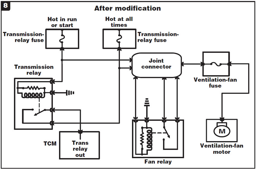
Note: The relay box is under the driver’s seat, and accessing it will require removal of the seat from the floor. Then the relay-box cover will have to be removed for access to the relay and the wiring.
- Ventilation-fan relay & wiring package. . . . . . . . . CFA1H040

June 2010 Issue
Volume 27, No. 6
- 4L60/65/70-E: Pump and input-shaft usage
- GM 6L80: Slips in forward, sets DTC P2728
- Freightliner/Dodge Sprinter: 722.6/NAG1 limp mode