An understanding of hydraulics is essential for properly diagnosing and repairing transmission problems. This article is one of a series by Sonnax exploring how valves and hydraulic circuits work and what results when they quit functioning correctly.
Some of the smallest valves in an automatic transmission are the check valves. They come in various designs, including checkballs, capsules and assemblies
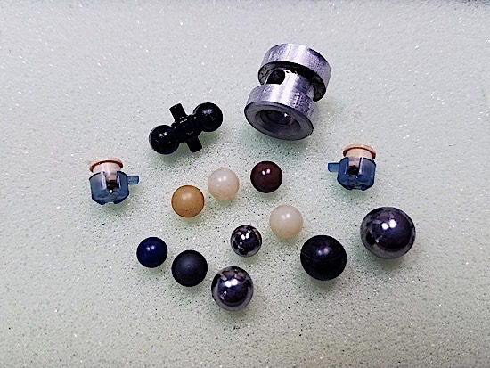
Their function is relatively simple: to direct flow into — or prevent flow from entering — specific circuits. While they are not very complex in design or purpose, they can cause significant performance problems if you aren’t careful.
One of the simplest check valve designs is the checkball. These typically reside in the worm tracks of a valve body or case and have a couple of associated separator plate orifices. A well-known example is the #8 checkball in the 4L60-E.
When functioning correctly, this checkball controls the 2-4 band apply during a 1-2 upshift and proper band release during a 2-1 downshift. The simple hydraulic circuit in Figure 3 shows the checkball in both applied and released states.
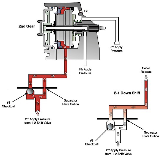
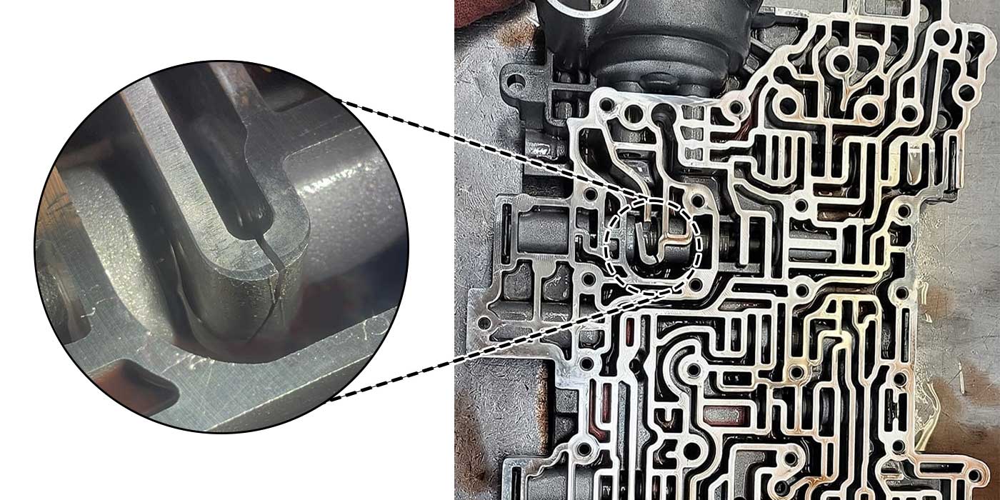
In 2nd gear, oil pressure and fluid seats the #8 checkball against separator plate and is routed through a small orifice to the 2nd/4th servo. This orifice reduces the flow to help cushion the band apply to provide a smooth shift. During a 2-1 downshift, 2nd clutch oil is exhausted from the servo and unseats the checkball. This allows for a quicker, but still controlled, release of the band. A common problem that occurs at this location is that, over time, the OE steel checkball beats against the softer separator plate, distorting the checkball seat, similar to that shown in Figure 4.
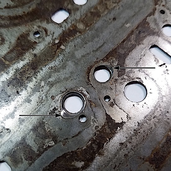
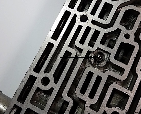
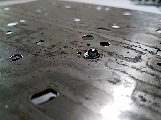
This gradually increases the hole size, which allows exhaust flow to increase and create 2-1 downshift clunks as the band releases too quickly. The hole will often get so large that the checkball sticks in it (Figure 5). This results in a slightly slower downshift to first, as the exhaust must all flow through the small orifice, preventing timely release of the band.
When a separator plate gets damaged to this degree, it needs to be replaced. To prevent repeat failure of this type, it is best to replace the steel checkballs with imidized plastic balls of the same size. This material has lower impact to the plate, is wear-resistant and conforms better for a reliable seal. Checkballs are also used in “bathtub” casting ports, where they are directing flow at three circuits. A common example of this is the #1 checkball in the 6L80 (Figure 6).
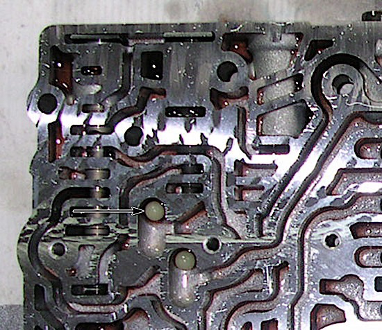
This soft, plastic, OE checkball will shuttle back and forth in the casting pocket, directing Drive flow to the 2-6 clutch/1-2-3-4 CL feed circuit in forward gears. During Drive 1st, with output speed over 100 RPM, Drive 1-6 fluid from an unstroked clutch select valve #2 (shift solenoid 1 off) seats the checkball to the right (Figure 7).
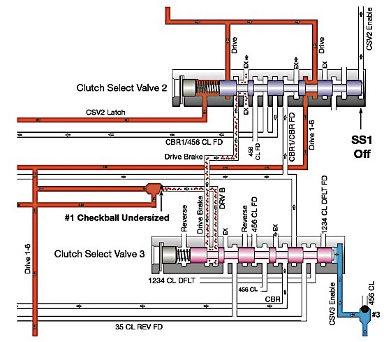
When in drive 1st at a stop, or with output speed under 100 RPM, engine braking occurs. The computer turns the shift solenoid on, stroking the clutch select valve #2.
This results in Drive Brake (DRV B) fluid seating the checkball to the left, and the low-reverse clutch applying via CBR1/CBR FD fluid pressure. This constant back-and-forth movement of the #1 checkball, especially in stop-and-go traffic, causes erosion of its soft plastic so the ball either becomes stuck in the separator plate or goes through the plate altogether.
This can result in no forward gear, even though Reverse remains fine. The best solution is to replace the plate (if damaged) and replace the soft white plastic checkball with a wear-resistant, imidized ball. This bathtub checkball wear is not a new problem. ZF dealt with it in the 1990s in the ZF5HP30 when the “F” clutch checkball would wear and blow through the separator plate, causing no Reverse
ZF created an innovative solution in later transmissions by designing a “teeter-totter” style checkball for typical bathtub locations (Figure 8)
This design prevents the wear from ball shuttling, but still allows for a ball to seal two different orifices for flow control. Another uniquely designed check valve was introduced by Aisin Warner in the AW55-50SN. These little plastic capsules (Figure 9) function just like a single checkball. The flat, cream-colored plastic top seals against a separator plate orifice due to slight spring force exerted from the remainder of the assembly.
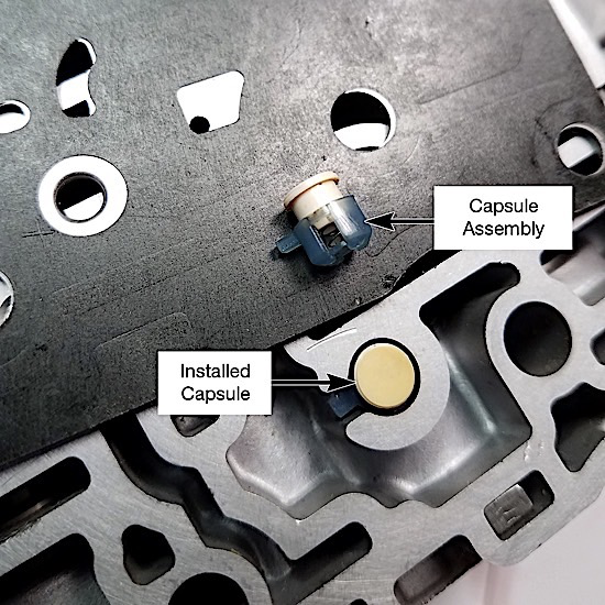
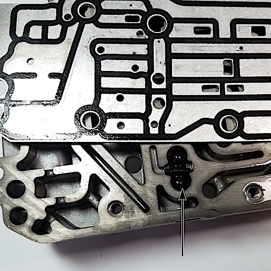
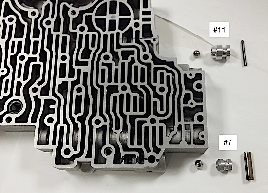
The plastic bottom has an anti-rotational tab that helps secure it in the valve body casting. The good news is that these do not damage the separator plate or shrink and go through the plate. However, harsh shift complaints could be the result of an assembly that is installed incorrectly, mechanically stuck or missing. Other check valve three-piece “assemblies” that function like a bathtub checkball are typical of the #7 low/reverse and #11 3rd clutch/Reverse checkballs in the 4L80-E (Figure 10).
As seen in the simple schematics in Figure 11, these assemblies direct fluid to the rear band apply and 3rd/Rev circuits from one of two circuits, while blocking the other circuit.
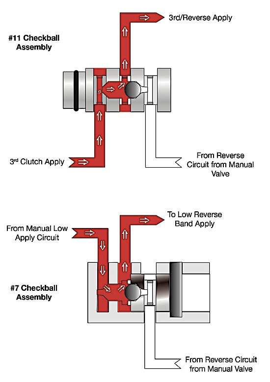
Because these steel balls don’t interact directly with the separator plate, there is no risk of plate damage or ball shrinkage. However, the soft aluminum seats and outside diameters can wear, resulting in gear slips, burnt clutches or delayed or no Reverse. Typically these will show significant visual wear. So, while check valves are fairly simple in design and function, they can cause various shift issues and clutch failures when not working correctly. A few simple techniques during your rebuild can save you time and money.
- Note locations of checkballs during disassembly using a scribe or camera, and cross-reference this with OE or aftermarket organization tech information. These small part locations commonly change as OEMs update their transmission designs.
- Virtually any check valve application can be vacuum tested for sealing integrity. Test the associated orifice by drawing vacuum in the direction that will also seat the check valve or checkball. Ideally, a vacuum reading of 23”–25” Hg should result for best function. Vacuum test guides for dozens of transmissions that show exactly where to test are available free at www.sonnax.com/vactest.
- Replace or repair damaged separator plates and consider replacing steel or soft plastic checkballs with imidized plastic to prevent future wear or shrinkage issues.
- During reassembly, verify all of the checkballs are accounted for and installed correctly. There’s a forest of missing checkballs somewhere (Figure 12), each representing a dissatisfied customer and an expensive comeback.

Location: Atlanta Botanical
Garden. TD
Maura Stafford is a Sonnax product line manager for transmission components and remanufactured valve bodies. She is a member of the Sonnax TASC Force (Technical Automotive Specialties Committee), a group of recognized industry technical specialists, transmission rebuilders and Sonnax Transmission Company technicians.