Technically Speaking
- Subject: Use of counterbalance pistons in clutch drums
- Units: TF60-SN (09G/09K/09M)
- Vehicle Applications: Audi, BMW, Volkswagen
- Essential Reading: Rebuilder, Diagnostician
- Author: Wayne Colonna, ATSG, Transmission Digest Technical Editor
Starting with a few four-speed automatic transmissions, increasing with the five-speeds and more so with units having six or more speeds, it is interesting to see the use of counterbalance pistons in clutch drums that drive the planetary system. Since drive-style clutches are rotational, there is a tendency for centrifugal force to creep the clutch on when it is not in use, which could cause premature damage to the frictions.
As a preventive measure, there is a balance area in each of these clutch packs in front of the piston. A slight amount of fluid pressure is supplied to this area to balance centrifugal head oil behind the apply piston, neutralizing its effect. In ZF 6HP26-style transmissions this feature is referred to as “dynamic pressure balance.” GM’s 6L80 operates in a similar manner, and the circuit used to provide fluid into these balance pistons is called the compensator feed fluid.
This feature of the clutch assembly is really a by-product or an additional benefit to what is really the main reason for the strategy. And that is that it gives the computer greater control over the engagement and disengagement of the clutch pack through the solenoids, which ultimately improves gear-shift comfort.
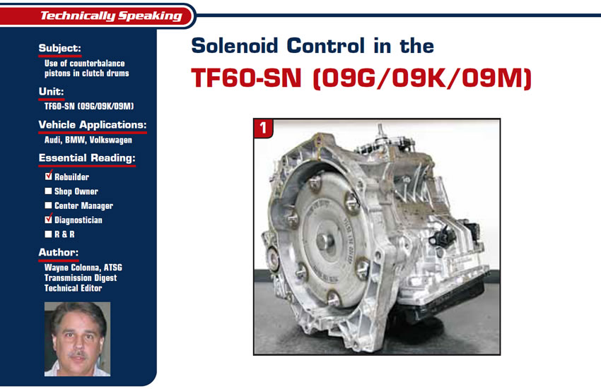
The six-speed TF60-SN (Figure 1) used in BMW, Audi and Volkswagen vehicles makes full use of this strategy. Interestingly enough, lube pressure is used as a feed into the counterbalance-piston area.
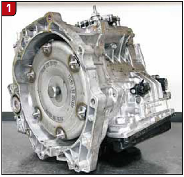
Figure 2 provides a clutch-application chart, and Figure 3 identifies the solenoids used to control the shift timing as well as clutch-pressure control and shift overlaps.
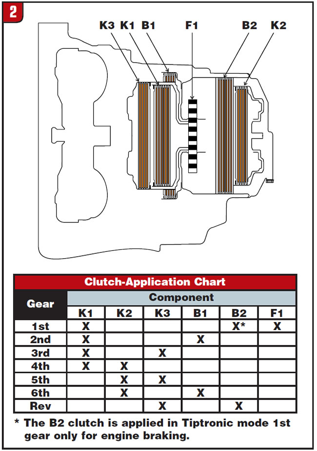
Figure 4 provides an overview of the solenoid shift strategy as it compares with the clutch application.
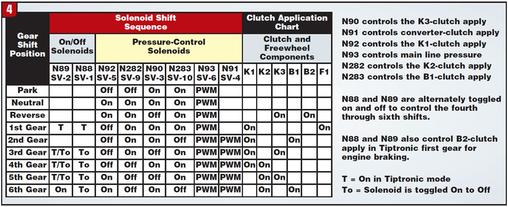
With the exception of the N91 converter-clutch-apply solenoid, all the other remaining pressure-control solenoids (N90, N92, N93, N282, N283) supply full pressure when they are in the off state. When they are pulsed fully on, they block pressure from entering their respective circuits. The N88 and N89 solenoids are typical on/off solenoids; however, during certain shifts the computer toggles them rapidly for a short time.
The use of these solenoids in conjunction with balance pistons provides greatly controlled shift feel. When these balance pistons lose pressure, harsh shifts are usually result, since the balance control of the piston is lost. And this is the type of drivability complaints we will become more familiar with as these types of transmissions begin to visit the shops for repair.
To take a closer look at the computer strategy of these solenoids we hooked up a laptop-based program called the VAG-COM from Ross-Tech, of Lansdale, Pa. When it was up and running (Figure 5), we selected the control-module mode. The next screen (figure 6) allowed us to select the TCM. Once we were in (Figure 7), we selected measuring blocks. The measuring blocks allow you to observe data stream of various inputs and outputs and to have the ability to record (log) data while driving.

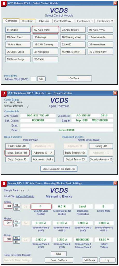
When we entered the measuring-block area (Figure 8), you will see that measuring-block group 004 provides some data related to gearshift position and TPS percentage while groups 007 and 008 present all the pressure-control solenoids in amps. The N88 and N89 are shown only as off by a 0 number and on with a 1 number. When you’re looking at the amperage of the pressure-control solenoids, 0.100 amp indicates that the solenoid is off, applying pressure to its respective circuit. When you see 1.000/0.990 amp, it indicates that the solenoid is turned on, blocking pressure from its respective circuit.
In Figure 8 we can see that we are in Park and that both the N88 and N89 solenoids are off. N92 and N282 are off while N93 and N283 are on. N93 is the pressure-control solenoid, so when that solenoid is on, line pressure is down. N91, the PWM TCC-control solenoid, is off so converter-clutch apply is off. Figure 9 shows the transition from the Park position into Drive. Only clutch-pressure-control solenoid N92 is off, applying the K1 clutch for a first-gear engagement.
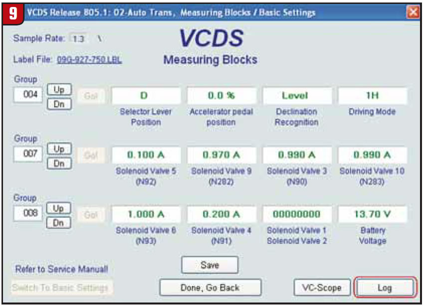
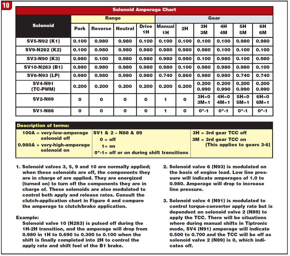
Figure 10 is a solenoid amp chart showing what the VAG-COM revealed throughout all the ranges. When you see the letter H next to the gear it means the converter clutch is off. When you see the letter M it means the converter clutch is applied. Be sure to read the notes provided for Figure 10.
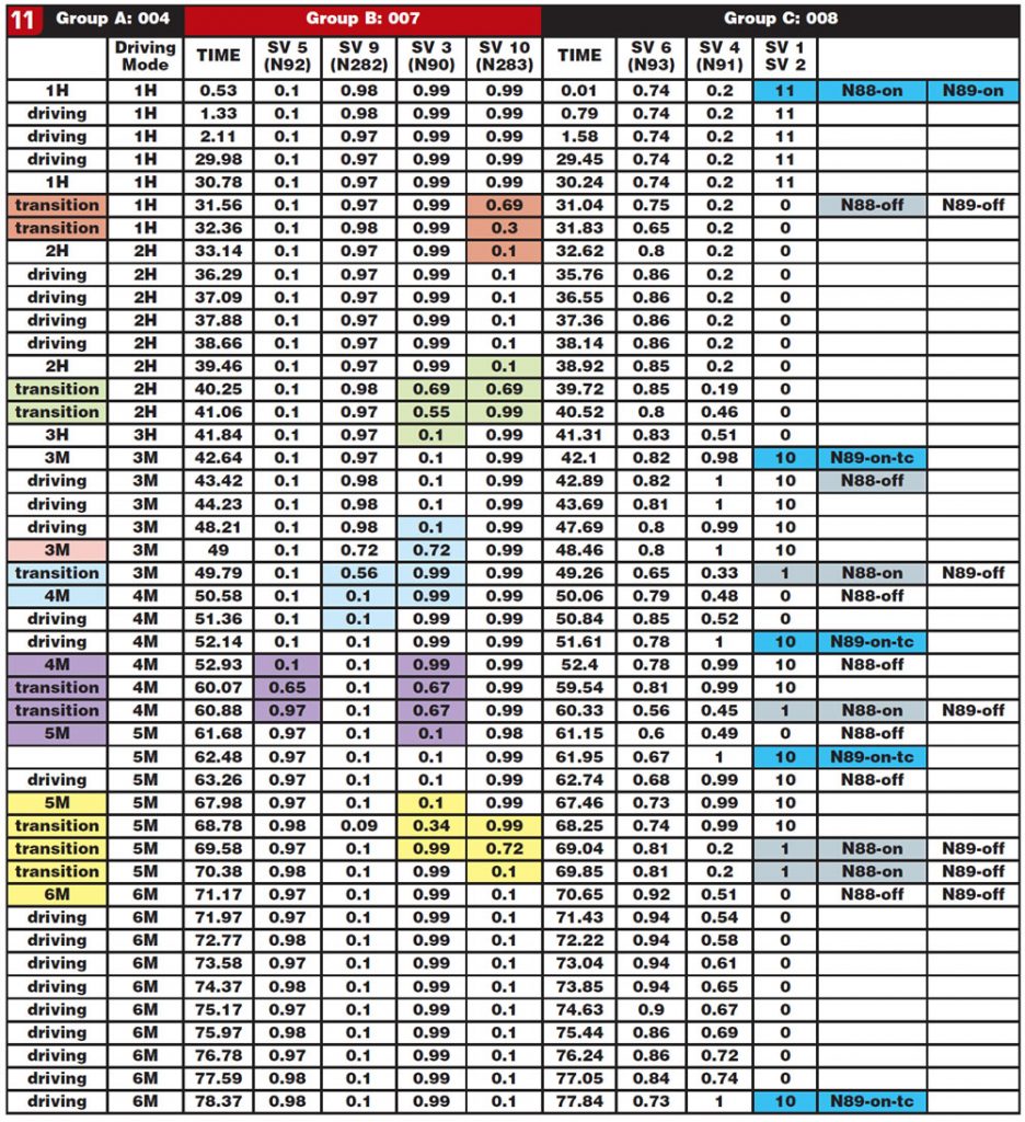
When it all makes sense to you, Figure 11 is a recording showing all the activity of each of the solenoids as we shift in Tiptronic mode from first all the way to sixth gear, including the converter clutch being applied and released. The highlighted areas provided in the movie point out solenoid shift transitions as the transmission is shifting through each of the gears. Compare this with the “time” column so you can see how quickly the computer can control these solenoids. Considering this along with the drive-clutch drums being equipped with balance pistons, the clutch apply and release can respond more rapidly to these commands than they could without them.


