Technically Speaking
- Subject: Suspension problem mistaken for a transmission concern
- Unit: F4A33-1
- Vehicle Application: 1995 Mitsubishi 3000GT
- Essential Reading: Rebuilder, Diagnostician
- Author: Wayne Colonna, ATSG, Transmission Digest Technical Editor
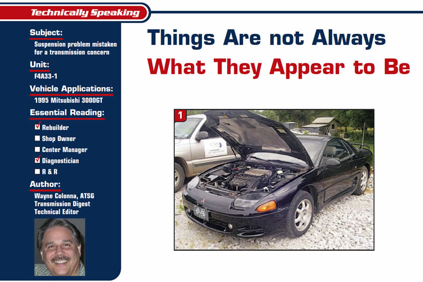
We received an interesting phone call on ATSG’s technical hotline regarding a 1995 Mitsubishi 3000GT (Figure 1) with an F4A33-1 transmission. Originally, the vehicle was in another facility where the original transmission had been replaced with one bought from an online marketer over the Internet.
Unfortunately for the owner this exchanged unit did not work correctly. Since the facility did not do transmission work the owner took the car to Chris Colucci at CNS Transmissions in Walnut, Miss. Chris saw that the vehicle was in a failsafe condition with lights blinking on the dash. The DTCs he extracted revealed gear-ratio-error problems. Upon learning that the transmission had been replaced, he put 2 and 2 together and realized that they might have installed a transmission with an incorrect ratio.
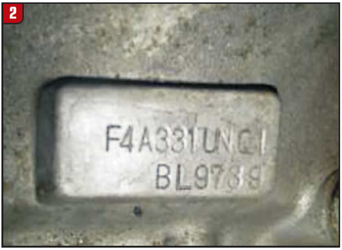
Embossed on top of the bellhousing was the code F4A33-1UNQ1 (Figure 2). Using the vehicle’s VIN, Dave at ATSG was able to determine that the vehicle should have had a transmission with the code F4A33-1MNQ7. The U in the code for the transmission that had been installed indicates a 4.367 final-drive ratio. But the one that is supposed to be in the car is an M, which has a 3.958 final-drive ratio. So Chris’s hunch was right. To the owner’s benefit, Chris was able to get the original transmission returned from the online company. He then rebuilt the transmission and installed it and erased all the codes.
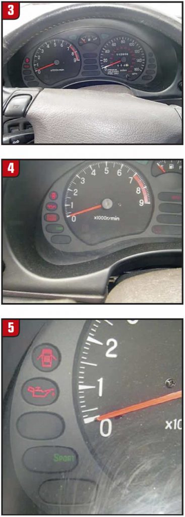
On the road test the unit operated flawlessly, yet there was a Sport light in the dash flashing away (figures 3, 4 and 5). So it was checked for codes and there were none present.
This is where the story gets a bit interesting. We are so accustomed to seeing transmissions today with sport, economy and power shift modes that with a sport light blinking, we wonder why there are no transmission codes.
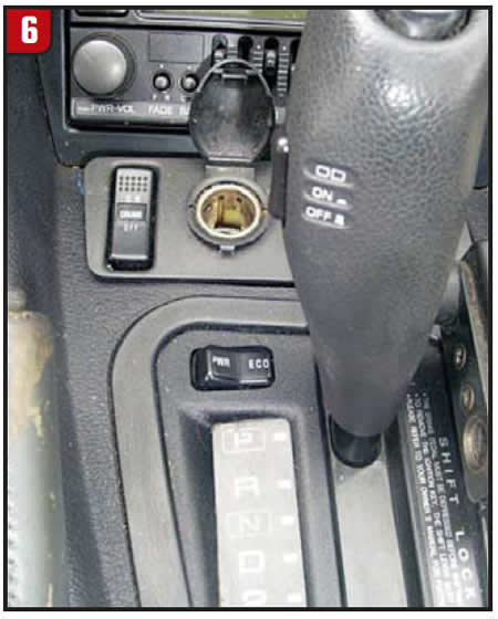
Looking at a wiring diagram for the transmission confirmed that there was no Sport-light circuit related to the TCM. Of course, on the shift console there were only Power and Economy modes; the shift lever contained the OD-on/off switch (Figure 6). However, by looking at the wiring for the instrument cluster, one would discover that there were both Sport and Tour lights being controlled by an electronic-suspension-control (ESC) unit behind the right-rear wheel well.
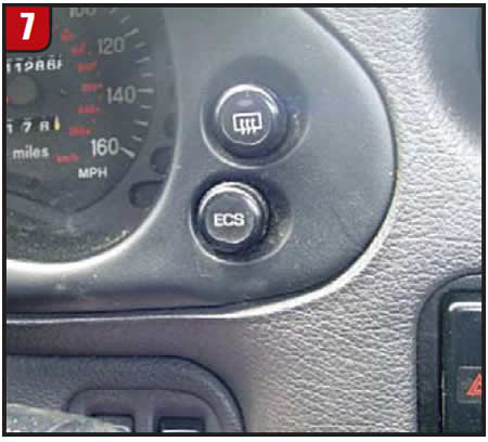
Another look at the dash revealed an ECS (Electronic Controlled Suspension) button (Figure 7).
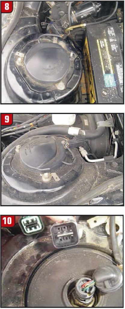
When I talked with Bob Nutall from Mitsubishi about this, he asked whether there were wires going to the tops of the struts. I called Chris, and he confirmed that there were, as you can see in figures 8, 9 and 10. This meant that the vehicle did indeed have the Electronic Suspension Control, and the flashing Sport light indicated some kind of failure with this system.
There is yet another element to this story. There is also supposed to be a “Tour” light in the dash to the left of the “Sport” light. And as you can see in Figure 4 there is plenty of room for this light. When this system has a failure, both of these lights should flash together. Well, the bulb for the Tour light was blown, so only the Sport light was flashing. This is why it appeared to be transmission related, not suspension related. Had the Tour light been operable and blinking with the Sport light, there would have been less chance of thinking the transmission was the problem.
When this ECS system is working correctly, upon startup the Tour light will be on. In the Tour mode, damping of the struts will switch automatically between “soft,” “medium” and “hard” as needed according to driving conditions as measured by sensors. The ECS button is used to switch over to Sport mode, in which damping is at the hardest setting at all times.
The sensors used as inputs to the ESC module to control the automatic Tour modes are shock-absorber-position detection switches for each of the four shock absorbers (two for each shock absorber); a G-sensor, which monitors up and down motion only; the VSS; TPS; brake switch; steering-wheel angular-velocity sensor; and, of course, the ECS button. Should there be a failure in one of these inputs the Tour/Sport light will blink.
Codes can be retrieved using a scan tool if it contains the proper software to communicate with the ESC module. Without such a scan tool, you can retrieve codes with an analog voltmeter or digital graphing meter or scope through the following procedure.
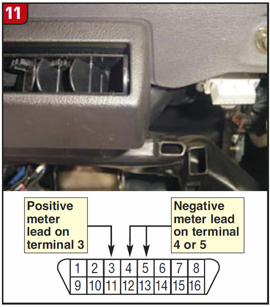
- With ignition off, connect voltmeter positive probe to terminal No. 3 of self-diagnostic connector, under right side of dash. (Figure 11). Connect voltmeter negative probe to terminal No. 4 or 5 of self-diagnostic connector.
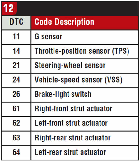
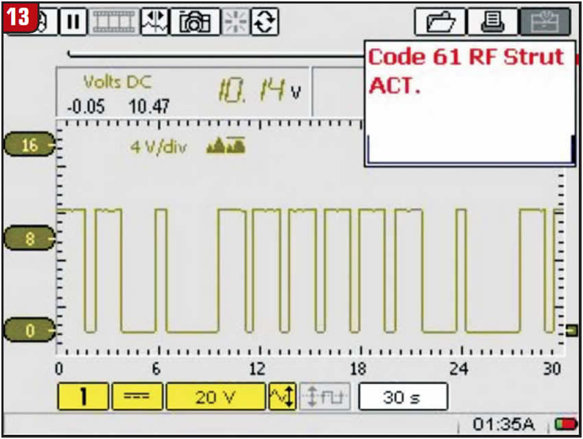
- Turn ignition on. Voltage signals generated are read as needle sweeps. The needle-sweep range is 0-12 volts. Longer-duration pulses are recorded as the tens digit of code, and shorter-duration pulses are recorded as ones digit of code. Codes are separated by a pause. If a digital graphing meter or scope is used there will be 0- to 12-volt blocks, with the wider blocks indicating the tens digit and the narrow blocks indicating the single digits. Figure 12 lists codes. This vehicle had a code 61 (Figure 13), which indicates a problem with the right-front strut actuator. A resistance check of the actuator motor in the shock absorber showed 8.1 ohms; the others measured 49 ohms.
So, in the end, the vehicle that came in with gear-ratio codes did not have the right transmission. The shop had to obtain the correct transmission, rebuild and install it, and road-test the car. And after another day in diagnostics because of a blinking Sport light that turned out to be a suspension problem and not a transmission concern, the car was finally delivered.
Gear-ratio codes usually mean a transmission is slipping, and a blinking Sport light could be reporting either that problem or another type of transmission failure. As shown by this situation, things are not always what they appear (or are assumed) to be.

Special thanks to Bob Nutall of Mitsubishi Motors for his technical assistance.


