Tech To Tech
- Author: Jeff Back
- Subject Matter: Lightning Strikes
- Vehicle Application: Various
- Issue: Tracing problems following lightning strike
It’s your best approach to tracking down the problem(s).
Problem description: Check electrical system. The battery goes dead after sitting a couple of days.
“Oh, yeah,” the customer said, “there was a lightning strike in the parking lot where I work that might have affected the van.”
Most of the time, when I get in a vehicle that has a problem associated with a lightning strike, it’s due to an insurance company adjuster trying to determine the validity of the claim.
I have had the opportunity to deal with several vehicles that were actually struck by lightning. Usually, various modules are fried; however, there was one that just threw me for a complete loop. The vehicle ran, but no electrical circuits in the body worked (windows, door locks, radio, etc.) I expected to find a main power circuit problem, but much to my dismay, there wasn’t a single blown fuse. The problem turned out to be on the ground side of the vehicle. The main body ground circuits that ran along the rocker panel under the driver-side doorsill were completely melted away.
This particular vehicle only had liability insurance, although the owner did say that four other vehicles in the parking lot had problems and all four were totaled by their insurance companies. “But,” he said, “they were closer to where it hit.” I informed my customer that if his vehicle did manage to become part of the lightning strike incident, that multiple modules may be involved and an accurate estimate would be difficult to obtain until after some investigation. The customer was fine with that and said to proceed step by step.
I started my drain tracing as I usually do by checking to make sure that none of the body input signals, such as the door handle and closure switches, were active – in other words, anything that would keep the body control awake. Getting a new Body Control Module (BCM) for a bad switch input is a mistake I see made often in our line of work. Something as simple as having the key in the ignition will cause an input that keeps that BCM awake.

Whenever possible I like to wait an hour before beginning a draw test with the vehicle properly at rest and with the hood open ahead of time. Next, I use a current probe – in this case, attached to my voltmeter set on the Milliamp (mA) scale. The probe I use outputs a voltage signal that is directly proportionate to the current it sees when set on the low scale. This one was showing more than 700mA (Figure 1).
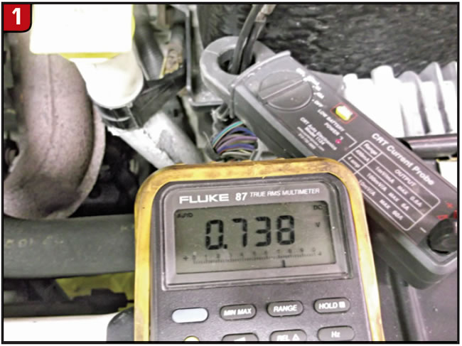
This is well over the accepted at-rest current. In fact, for this model I typically see less than 30mA of at-rest current.
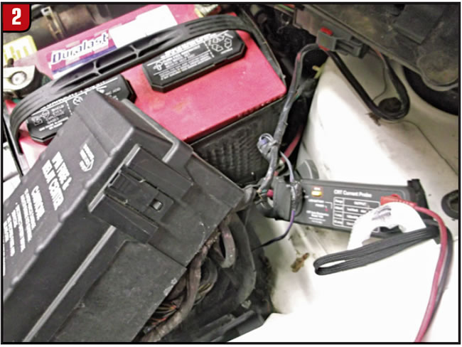
The next step was to find out where the excess current was going. I started this quest by eliminating one of the often overlooked but not uncommon causes: the alternator. By simply grasping the alternator’s feed and output circuits in the jaws of the probe, it was quickly eliminated as a suspect and I was able to move to the power distribution box (PDC) feed. This PDC had a quick release that allowed me to lift it up from the battery box for full access to its feed and output circuits. I measured the full current draw on the main feed (Figure 2).
I could then measure the voltage drop across each of the PDC’s fuses to see which circuits were carrying current. So far I hadn’t had to break any circuits to do my testing and risk waking any modules. By using the voltmeter’s millivolt (mV) scale I got a reading on two fuses.
Next, I went back to the current probe and read the current on the circuits leaving those two fuses under the fuse box and saw that one of them was carrying most of the current. By using the wiring diagram, I was able to see that it was the BCM carrying the current. With no discernible inputs, I made the determination that the module was the culprit. Before replacing the module, I printed out the connector views and pin-checked each circuit to make sure I hadn’t overlooked any circuits that I couldn’t parameter check.
“Test – don’t guess” has always been my motto. I like to think I have done all I can before replacing a nonreturnable module. I hate finding myself in the unenviable position of explaining to the customer the next “other necessary thing” that has to be done to fix the vehicle. I realize that sometimes it takes fixing one problem before finding another, but I’m not a big believer in the “chain reaction” theory that some use to explain all the parts they needed to replace to fix one problem.
The new BCM took care of the drain issue. I then was able to get 27 mA of “at-rest” current. I took the vehicle down the road for a test drive and discovered that the transmission was running in limp mode and the shift indicator lights were boxed and blinking. The scan tool showed no data coming from the transmission control module.
So the question became: “How many more modules are going to be a problem and how do I get to a bottom-line estimate?”
The best way to proceed from there, in my opinion, was to make the customer aware of the possibility that there other modules may have been involved and I needed basically an open-ended authorization to continue.
After getting more time authorized to do further testing, I printed out the wiring diagram for the transmission control module (TCM) and the connector view.
The TCM showed a P 1684 code, which just says the TCM has been disconnected. I figured I set that when I removed the connector to get the pin cover off.
I did the power and ground test and got 12 volts on the battery circuit and good grounds.
Next, I checked the trans solenoid control circuits and couldn’t get any voltage on any of the solenoid circuits. I tested the transmission controls relay control circuit and couldn’t get any voltage there either. After back-tracing the control circuit, I discovered that the integrated power module (IPM) had an open in the circuit between the trans relay control circuit and the circuit from the TCM.
Since the PRND31 indicator was showing boxes around the letters, I continued measuring the voltages and comparing them to the diagram in the diagnostic chart. The numbers didn’t agree with the chart and the data voltage seemed odd, with three of the four data switch circuits at 3.5 and the fourth one reading 7.4 volts.
The vehicle still started but ran with the transmission in limp mode. The park neutral start switch is separate from the PRNDL switch.
This made three more components look to be possible victims of the high voltage from the lightning strike.
The customer was very cooperative in giving the authorization for the repairs and was thankful that we were even willing to work on the problem. I found out later that the customer had been to several places and had difficulty getting anyone willing to diagnose a lightning strike-related problem.
Jeff Bach is the owner of CRT Auto Electronics in Batavia, Ohio. He can be reached at [email protected].
This copyrighted article is reprinted with the permission of AutoInc., the official publication of the Automotive Service Association (ASA). To learn more about ASA and its commitment to independent automotive-service and repair professionals, visit www.ASAshop.org or call 800-272-7467.