
Technically Speaking
- Author: Wayne Colonna, Technical Editor
Several 1989-1995 Mercedes vehicles using the 722.3 or 722.4 transmission employ a device called the “upshift-delay vacuum actuator.” For this article, I will refer to it as the UDVA.
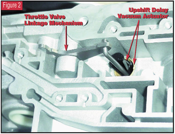
Figure 1 is a cutaway view of a single-diaphragm design. The throttle cable enters the UDVA at the upper-right corner and is attached to a plastic actuator piston inside the assembly. This actuator piston then operates a linkage mechanism inside the transmission that depresses the throttle valve in proportion to throttle opening (see Figure 2).
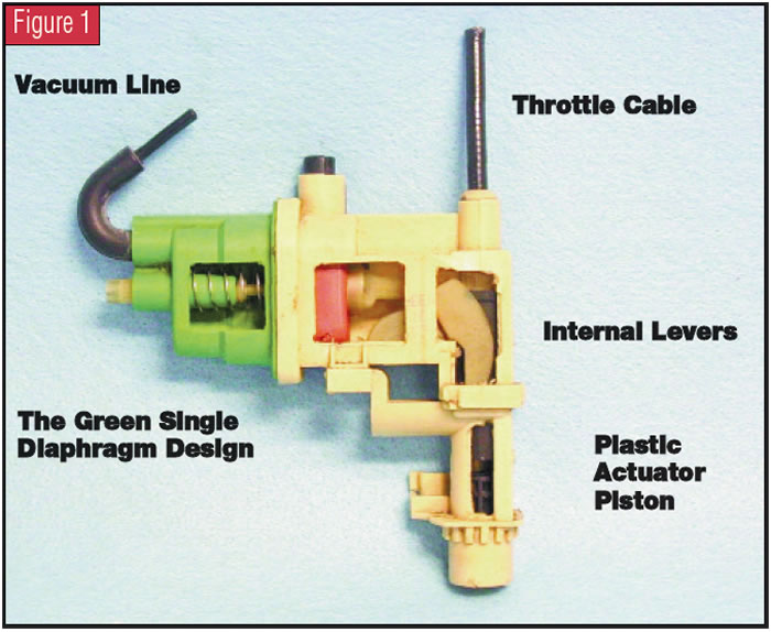
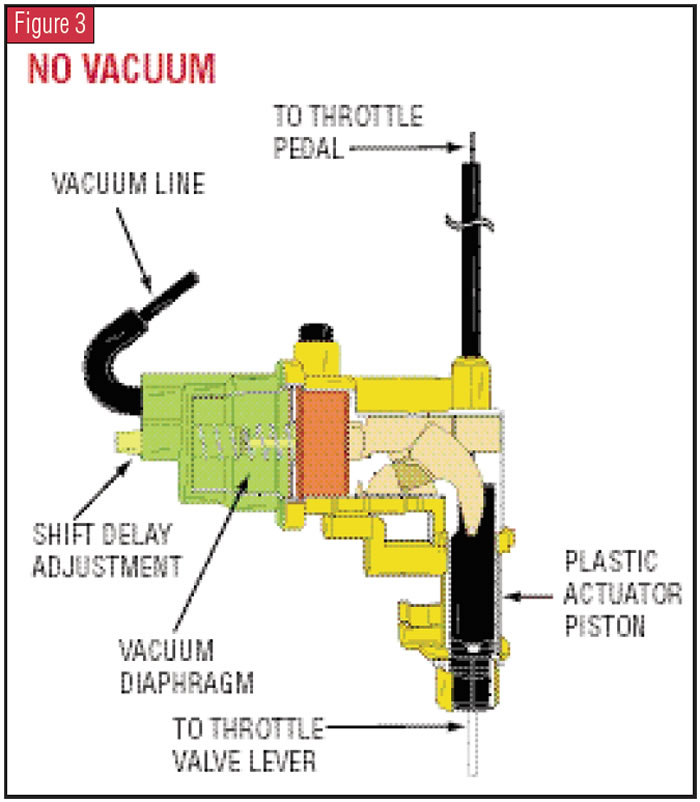
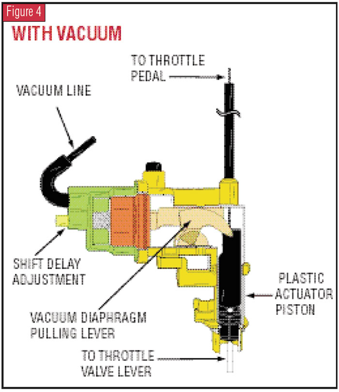
At the left side of the actuator assembly is a single green diaphragm. This diaphragm is attached to a vacuum-supply line. When vacuum is present, it operates internal levers within the assembly that override the throttle-cable signal by pulling on the plastic actuator piston. Figure 3 illustrates the assembly when vacuum is not present, and Figure 4 illustrates what occurs when vacuum is present.
Vacuum is supplied to the assembly to delay upshifts when the vehicle is cold in order to provide more-rapid heating of the catalytic converter. The length of time that the shifts are delayed depends on how long vacuum is supplied to the UDVA. The length of time the vacuum is supplied is dependent on engine temperature, vehicle speed and computer-controlled timing. The range of each input is dependent on the year, model and the type of control system with which the vehicle is equipped.
In general, the various computer systems command vacuum to be supplied to the green diaphragm when the engine-coolant temperature is in the range of 32° F to 104° F or less (0° C to 50° C or less) and the vehicle speed is between 6 and 34 mph (10 km/h to 52 km/h). Once these conditions are met, vacuum may be supplied to the UDVA from as little as 15 seconds to as long as 21⁄2 minutes.
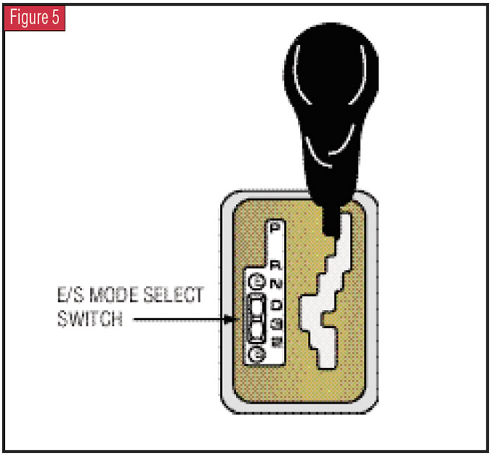
With various vehicles equipped with a Sport/Economy Mode select switch (see Figure 5), a second-design UDVA incorporates an additional diaphragm that is red (see Figure 6). It, too, overrides the throttle cable and delays upshifts when the sport mode is selected. (Other vehicles that have this mode select switch are designed to use the same green single diaphragm instead of having and using the additional red diaphragm.)
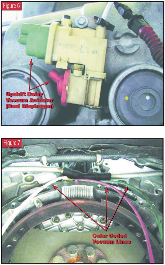
In some instances, these diaphragms are fitted with color-coded vacuum lines as shown in Figure 7. The pink line goes to the red diaphragm, the green goes to the green diaphragm and the white line is for the vacuum modulator. You must take care to ensure that these vacuum lines are fitted correctly, especially if they are not color coded.
The late-shift problem occurs when constant vacuum is supplied to either one or both of these diaphragms. Vacuum is supplied to these diaphragms through “upshift-delay switch-over valves” that the computer turns on and off via the ground side of the switch.
Figure 8 shows a simple diagram for vehicles using one switch-over valve and one vacuum-hose connection, and Figure 9 shows a simple diagram for vehicles using two switch-over valves. Figure 10 shows a simple diagram for select vehicles with one switch-over valve and a mode select switch.
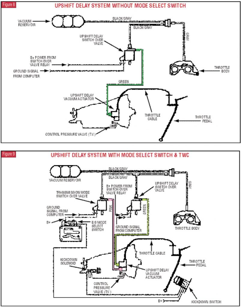
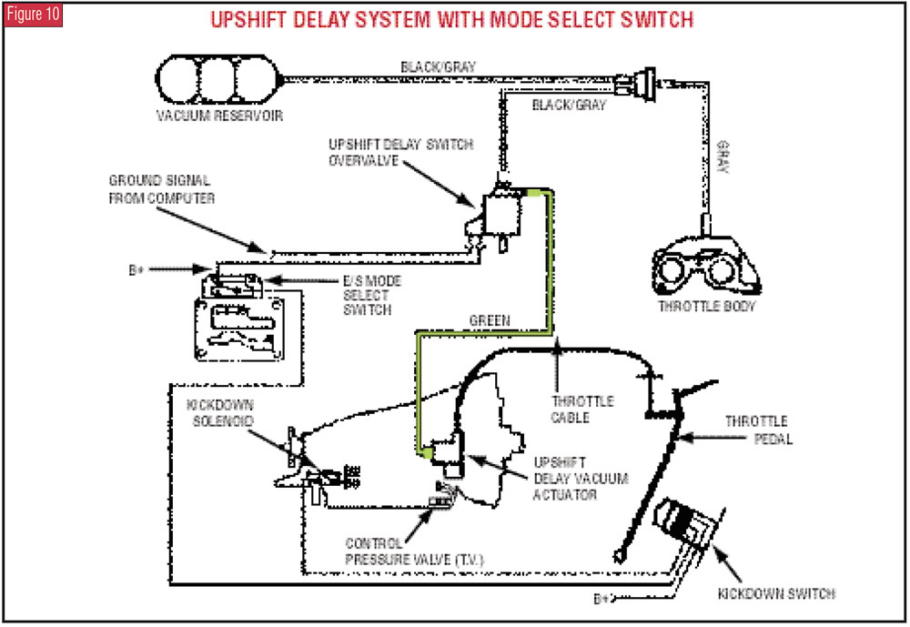
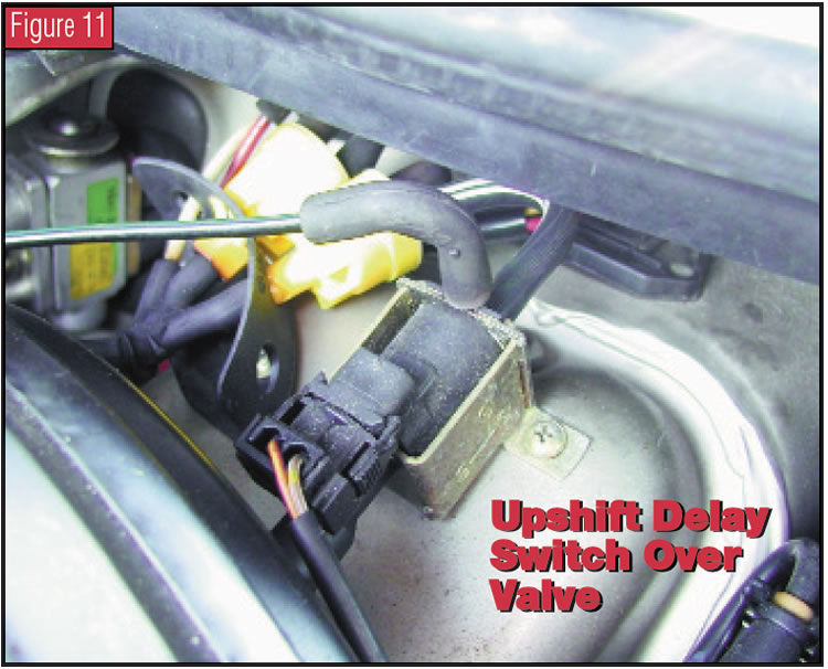
Figure 11 shows a switch-over valve. Usually, this vacuum switch sticking in the open or energized position and causing constant vacuum to be supplied to the UDVA produces the late-shift complaint. One simple check is to warm up the engine and set the mode select switch, if the vehicle has one, in the “E” position. There should be no vacuum supplied to either diaphragm. If there is, the appropriate switch-over valve will need to be investigated.
In Figure 12, a Vantage meter in split-screen mode shows system voltage on the power wire and 0 volts on the ground wire. This is the switch in its “on” state. Figure 13 is the switch in its “off” state after the computer has ceased grounding the switch.
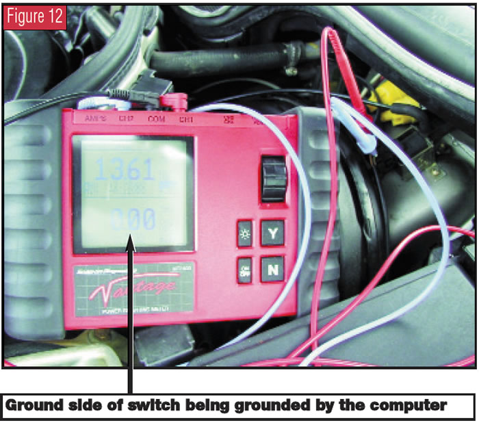
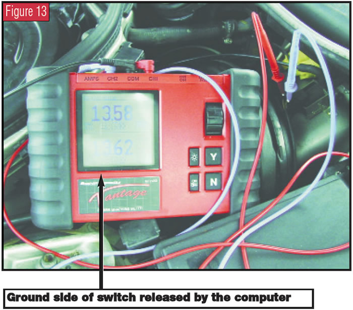
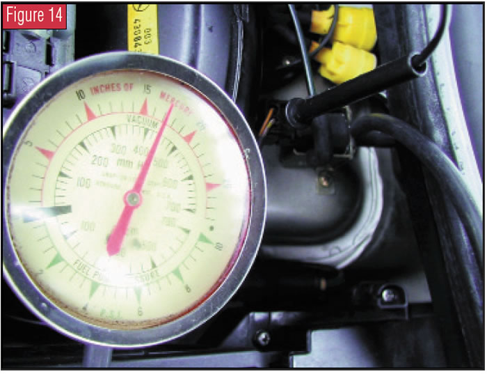
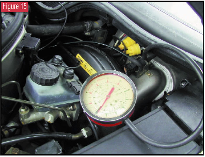
When the switch is energized as Figure 12 illustrates, a vacuum supply should be sent to the UDVA as indicated by the gauge in Figure 14. When the computer turns the switch off by releasing the ground (refer to Figure 13), vacuum to the UDVA should be blocked, as shown on the gauge in Figure 15. This is the proper operation of both the computer and the switch.
When you’re checking a vehicle with this late-shift problem, if the computer commands are correct but a constant vacuum is applied to the UDVA, the switch is defective and will need to be replaced. A defective computer keeping the switch grounded is an extremely rare occurrence, and it’s highly unlikely you will encounter such a failure.
You will run into more cases of the ground wire being shorted to ground, keeping the switch energized at all times and resulting in a constant supply of vacuum to the UDVA. Other times you may find a defective mode select switch. These are the most-likely failures after you have eliminated switch problems as the cause.


