Torque Converter Tech
- Author: Ed Lee
A 604 transmission with a 740 code led to many different approaches and attempts to troubleshoot the underlying problem. As the possible causes were narrowed down, the focus began to turn toward the converter. Replacing the converter with a factory unit eliminated the 740 code, and since the code would show up on any road test, this seemed like the perfect vehicle to identify the root cause.
Time after time, the faulty converter was removed from the vehicle and one change was made or a part replaced before the converter was reinstalled. After many days and many more R&Rs, the problem was found to be poor converter flow, caused by a solid fiber thrust washer between the cover and turbine hub.
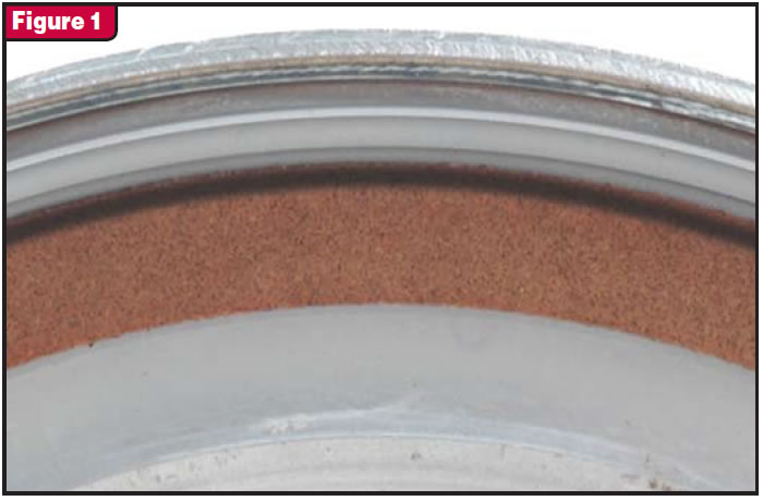
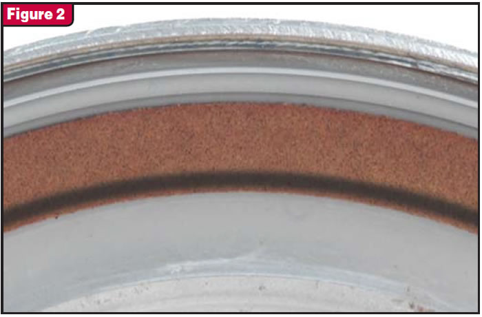
Finding the root cause was time consuming, but the information discovered will prevent the same mistake from being made repeatedly in the future. Some other information also was discovered during the process of inspecting the insides of many low-mileage converters in a short time. One was the uneven wear pattern on the new friction material. The 740 codes were proof that a TCC slip had occurred, but the technicians expected to see an even wear pattern down the center of the friction material. However, none of the converters had this wear pattern. Most converters had a dark wear pattern at either the inside or outside edge of the friction material (see figures 1 and 2). The mystery of why the 740 code happened may have been solved, but several new questions had come up.
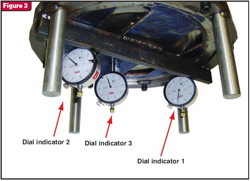
To better understand the uneven wear pattern on the new friction material, a test was set up. A fixture was devised to allow air pressure to be applied to the back of the TCC piston and record the deflection of the front of the piston at the same time. The deflection of the front of the piston was measured in three different places with three dial indicators. One of the dial indicators contacted the piston just inside of the friction material surface, one was by the ID of the piston, and the third was halfway between the other two (see Figure 3).
Since the front-wheel-drive Chrysler pistons range in diameter from 10.2 to 11.2 inches, the fixture was made to fit all sizes. A 2° taper was machined at the OD of the fixture where it contacts the OD of the piston. This kept the test equal with all the pistons and did not give any pivotal effect on any piston as they deflected forward. The IDs of the pistons are all the same. To make sure that pressure was acting on only the surface area of the piston, an OE turbine hub was attached to the front of the fixture. The OE hub was fitted with OE seals, and the pistons were free to move independently of the hub.
Since the area in front of the TCC piston is open to exhaust when the switch valve is stroked to the lockup position for TCC apply, the pressure in front of the piston remains at 0 psi anytime the clutch is applied. This allowed for open areas in the front of the fixture for observation of piston movement.
Since the pressure acting on the front cover of the converter is 0 psi in lockup mode, it was assumed that there was no deflection of the cover and the piston applied against a flat surface. We’ve all learned what happens when we assume. (As the old saying goes, to assume “makes an ass of u and me.”) The normal forces within the converter are continually trying to separate the turbine and the stator and the turbine and the impeller. These two forces, acting on the turbine, force it toward the cover. This force is transferred to the cover through the turbine hub and the thrust washer or bearing that separates them. The greater the acceleration of the vehicle, the greater the force within the converter. (Ballooning is a good example of this).
Normal acceleration will generate enough internal pressure to force the OE cover forward about 0.030 inch at the pilot. A billet cover will deflect about one-third this amount, or about 0.010 inch, at the same rate of acceleration. This forward force is increased greatly when the converter is in the TCC-apply mode, because the area in square inches of the surface of the turbine hub times the TCC-apply pressure (psi) is also acting on the cover. The piston never applies against a flat surface.
The test was done on six different pistons:
- 1) OE 604 stamped-steel piston
- 2) OE piston with 0.015 inch machined off the clutch surface
- 3) OE piston with 0.030 inch machined off the clutch surface
- 4) Uncut billet 604 piston
- 5) Billet piston machined 0.015 inch
- 6) Billet piston machined 0.030 inch.
The pressure that exerted force on the piston started at 20 psi and increased in increments of 10 psi until the pressure regulator read 90 psi. A second gauge was placed in line at the fixture to record any difference caused by a leak.
With all six pistons, both the gauge at the regulator and the gauge at the fixture read the same pressure, from 20 to 80 psi. When the regulator was bumped up to 90 psi, the gauge at the fixture would go up to only 84 psi. This was also true when any attempt was made to regulate the pressure even higher. It is interesting to note that the OE apply pressure is about 80 psi.
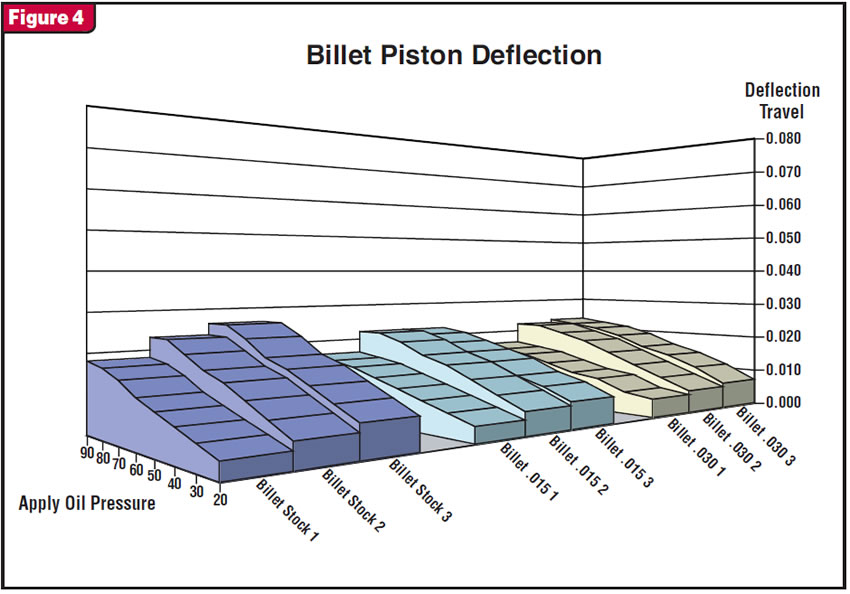
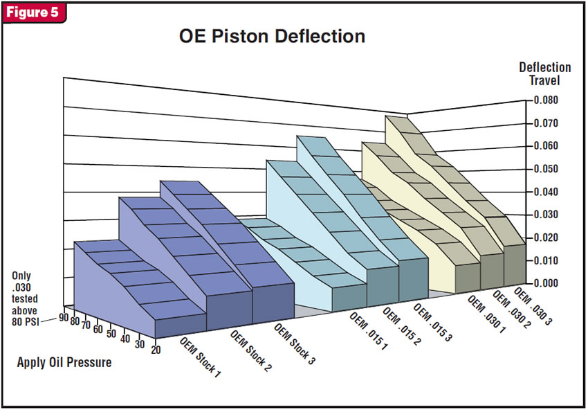
Starting at the pressure of 20 psi, the readings of the dial indicators were recorded, and each time the pressure that was exerted on the piston was increased by 10 psi, the new readings also were recorded. This then was graphed to show how the deflection of the pistons changed in relationship to the changes in pressure (see figures 4 and 5).
Some observations
- 1) The pressures being equal, the uncut OE piston will deflect almost twice as much as an uncut billet piston.
- 2) The OE piston is weakened by machining more than the billet piston. When the OE and billet pistons are machined a like amount, the difference in deflection is almost three times as much on the OE piston.
- 3) When 0.015 inch was machined from the billet piston, it actually had less deflection, because machining removed the 0.75° taper on the uncut piston.
- 4) The better the mating surfaces match, the better the seal for TCC apply. The difference in the amount of deflection between the piston and cover will shift the apply force to the outer or inner edges of the friction material.
- 5) The higher the pressures, the greater the deflection differences will be.
- 6) Piston deflection is inversely proportional to how rigid the piston is (the more rigid the piston, the less deflection). This may be why the newest front-wheel-drive Chrysler pistons are about 65 Rockwell. The downside is that they cannot be machined by conventional methods, not even carbide: They must be ground to resurface.
Some suggestions
- 1) To keep the angles of the mating surfaces as close to parallel as possible, use a billet cover and billet piston.
- 2) If you use a billet piston and an OE cover with an original lining, you may want to remove the taper from the billet piston. When the cover deflects more than the piston, the apply force is localized more toward the outside edge of the friction material (see Figure 1).
- 3) If you use an OE piston and billet cover, you will want to limit the amount of material that you machine from the piston to about 0.015 inch maximum. When the piston deflects more than the cover, the apply force is localized more toward the inside edge of the friction material (see Figure 2).
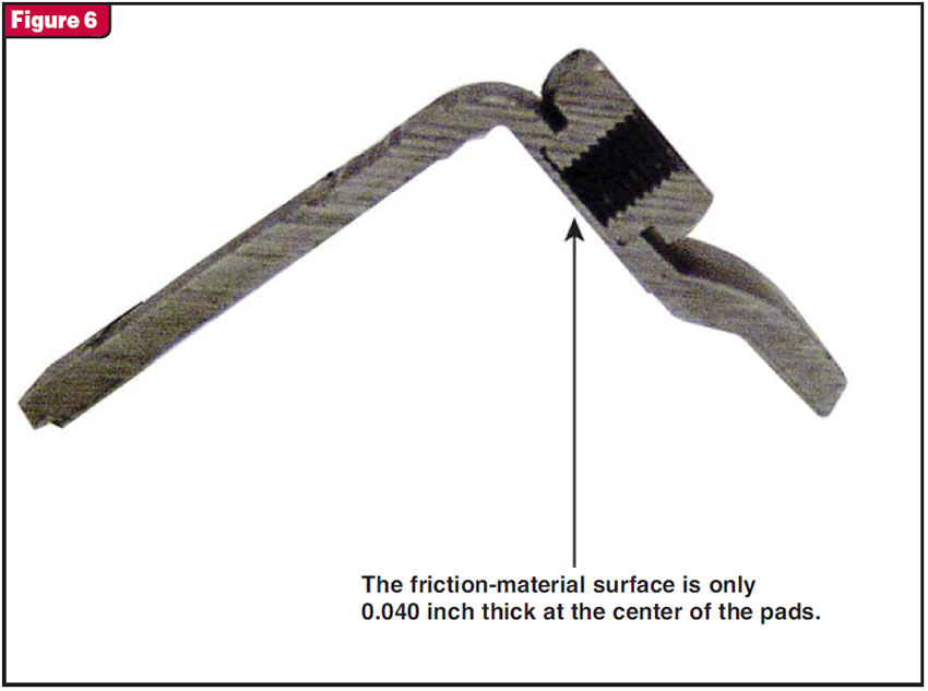
- 4) Use caution anytime you are machining an OE cover: The friction-material surface is only 0.040 inch thick at the center of the pads(see Figure 6).
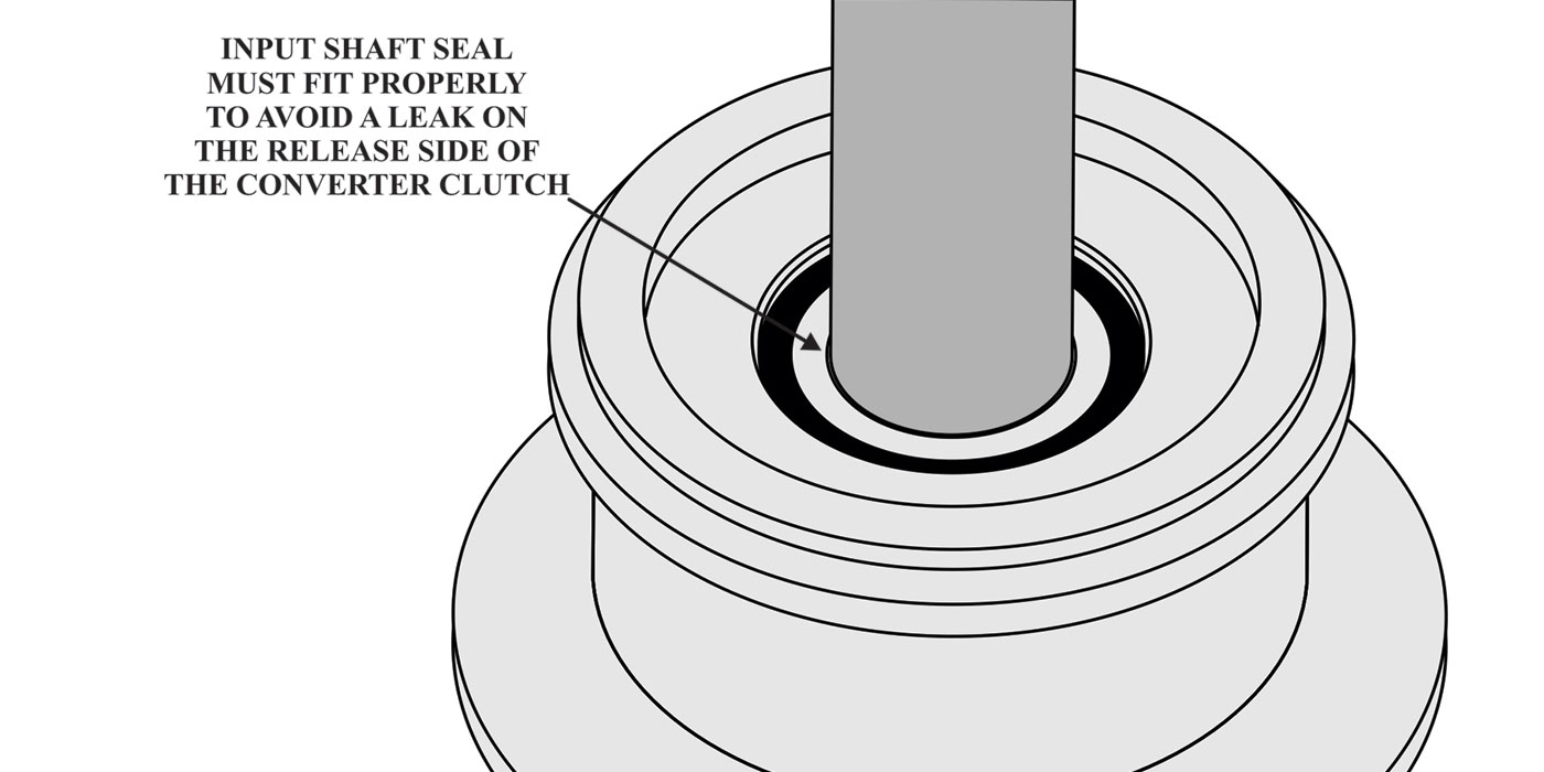
- 5) Knowing that the cover is always deflected forward at the time of piston apply is a good reason not to use drop-in linings. The turbine hub is held on the centerline of the cover by the bushing in the cover, and the TCC piston is centered by the turbine hub. Any amount that the lining is off center moves the lining up the angle of the apply surface of the cover, created by the deflection of the cover (uneven contact of the piston).
- 6) Measure the thickness of the piston inside of the spring retainer to see whether they have been machined. The uncut OE piston measures about 0.100 inch, and the uncut billet measures between 0.100 and 0.105 inch in the same area.

©2006 Sonnax Industries Inc.