
Technically Speaking
- Subject: Confusion regarding speed sensors
- Unit: RE4F04B
- Vehicle Applications: 2003 Nissan Altima
- Essential Reading: Rebuilder, Diagnostician
- Author: Wayne Colonna, ATSG, Transmission Digest Technical Editor
The RE4F04B transmission is no stranger to our technical hotline, for a variety of reasons. This article is about a self-inflicted injury that occurs every so often and, when it does, makes for a very bad day.
After work is performed that required the removal and reinstallation of the transmission, a complaint of no upshift occurs. As a result, code P0720 is stored for loss of an AT Revolution Sensor (OSS) signal. This is not to be confused with a P0500 VSS code and CAN communications codes U1000 or U1001.
Using a 2003 Nissan Altima as our example, the P0720 is referring to the three-wire Hall-effect revolution sensor, which sends a vehicle-speed signal directly into the TCM. The P0500 is referring to the two-wire AC-voltage speed sensor over the axle, which sends a vehicle-speed signal into the combination meter (instrument cluster) first. The combination meter then sends this signal to the ECM over the network.
One error is misunderstanding the difference between these two codes and the sensor to which each refers. P0720 has been misinterpreted to mean the two-wire VSS, and the sensor is replaced with no positive results. It is then checked with a meter, which shows a good signal, so the instrument cluster is removed and may even be replaced, yet the P0720 remains. We have even seen this error go as far as having the ECM replaced, all because of misunderstanding the code and its related sensor. When this two-wire sensor does fail, or the instrument cluster becomes faulty, the VSS signal in the cluster will not work properly or will not work at all. The instrument cluster no longer provides a speed signal to the ECM, causing the communication CAN codes to store along with the P0500 code.
When code P0720 is properly understood, what usually occurs is the sensor is quickly replaced and, of course, the problem remains. The next step that may occur is checking the sensor signal with a scope or digital graphing multimeter at the sensor itself. This being a Hall-effect sensor, one wire is a power supply, one wire is ground and the center wire produces a 0- to 5-volt pulse to the TCM. So it’s an easy-enough sensor to check. Just place the negative lead to ground, probe into the middle wire and run the wheels on the lift. If there is no signal and the sensor has power and ground, either the sensor is bad or the signal wire is shorted to ground. But in this scenario, a good signal is observed at the sensor, suggesting the TCM is faulty. The next step in this case would be to check the signal at the TCM. If this step were performed, it would reveal that this signal is not getting to the TCM. Could this mean that the signal wire is open?

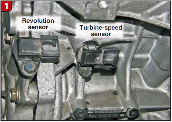
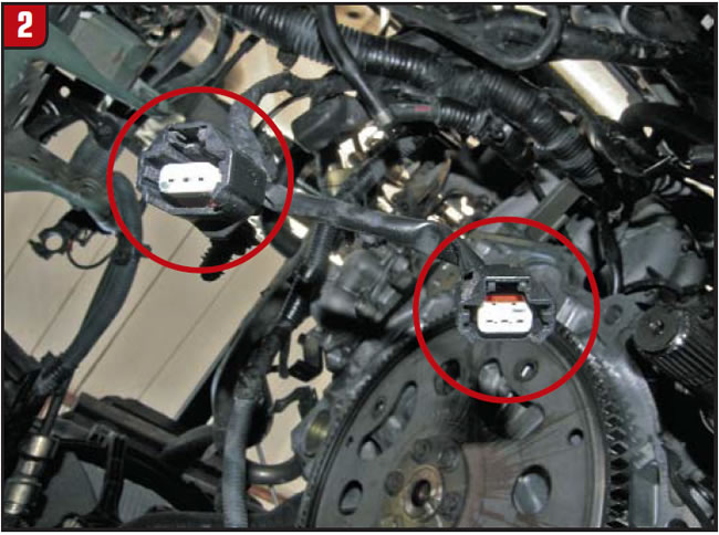
In Figure 1 you will notice that the revolution sensor is alongside the turbine sensor. When looking at the connectors for these two sensors (Figure 2) you will also notice that they are of the same configuration. This then allows for these two sensors to become cross-connected. When the sensor was being checked with a meter at the sensor itself, the signal coming out of the sensor was good but it was going into the turbine-speed input at the TCM.
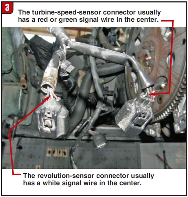
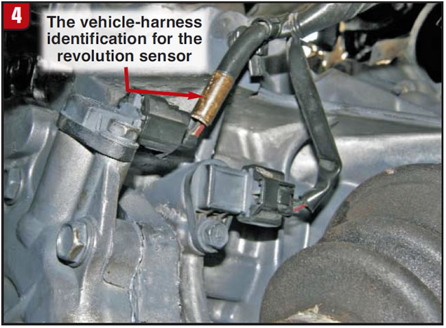
But wait a minute; if these two sensors were cross-connected, why wasn’t the turbine-speed sensor (TSS) sending a signal into the VSS input at the TCM? Good question. The answer is that the TSS is reading the forward drum, which is held stationary in first gear. There is no signal until a shift into second occurs. A simple swapping of the connectors is all that is needed to resolve the P0720 dilemma. Figure 3 identifies the color of the center signal wire for both the turbine-speed and revolution-sensor connectors to help you get them connected right the first time. If the vehicle harness is not deteriorated, the revolution-sensor harness is identified with white (Figure 4).
Since the subject is getting up to speed with the RE4F04B, it may be a good idea to mention the there is a difference between the RE4F04A and RE4F04B transmissions with regard to the forward-clutch drum. The low/reverse-clutch lugs on the drum excite the TSS, and these lugs are shallower in the A version and taller in the B version. If the A-style drum is used in a B-version unit, the air gap will be too great and you will get continuous P0717 TSS codes. This is a definite hair-pulling experience.
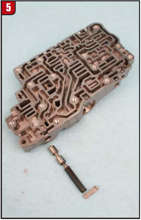
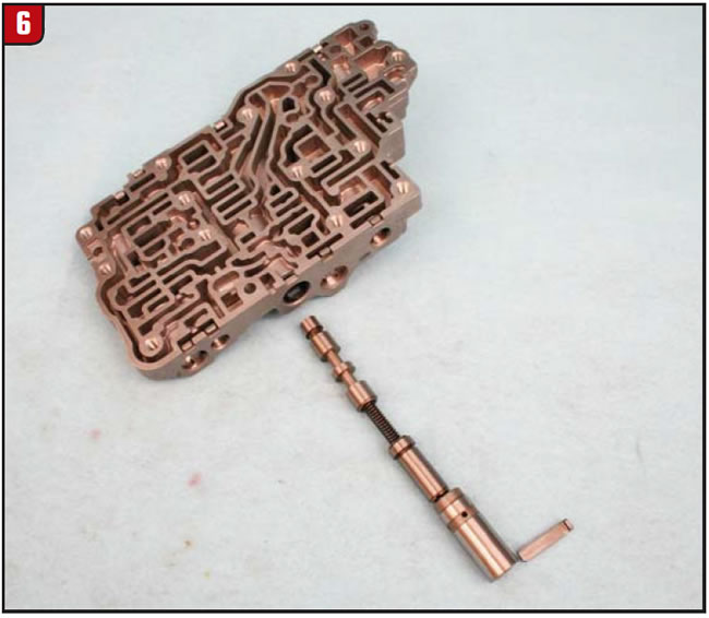
Another self-inflicted injury that comes up every now and again is a complaint of a good drive engagement but as soon as the throttle is depressed the vehicle stalls. The TCC solenoid is replaced (which includes all the other solenoids) and, of course, the problem remains. A common practice with the RE4F04A is to put in a firmer spring on the pilot valve, like the one seen in the RE4F04B in Figure 5.
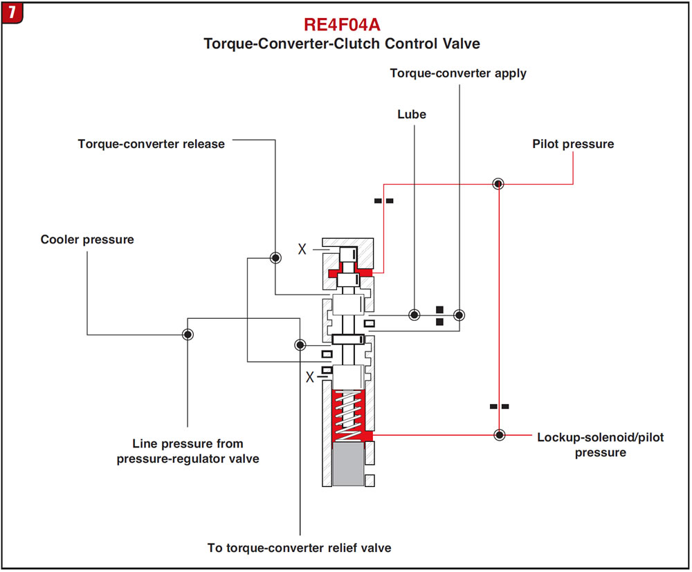
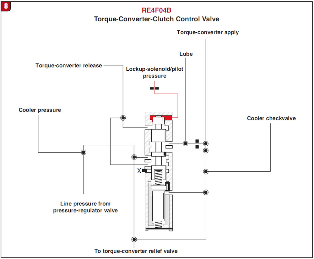
This works well in the A version to firm up the shifts, but in the B version it causes the converter clutch to apply. The reason for this is that the TCC control valve in the B version is configured differently from the one in the A version (figures 6, 7 and 8). Should a heavier spring be placed on a pilot valve in the B version, as soon as the throttle increases pilot pressure increases. This floods the TCC solenoid, which causes it to stroke the lockup-control valve, applying the clutch in the converter and stalling the engine.
One final and very elusive complaint that occurs quite infrequently is intermittent solenoid electrical codes. I say it is elusive because I have handled this only on the phone and have never seen it for myself. There are two ground wires that come down to the transmission (Figure 9). It is the little ground wire that gets left unplugged from the transmission (Figure 10), causing these intermittent solenoid electrical codes.
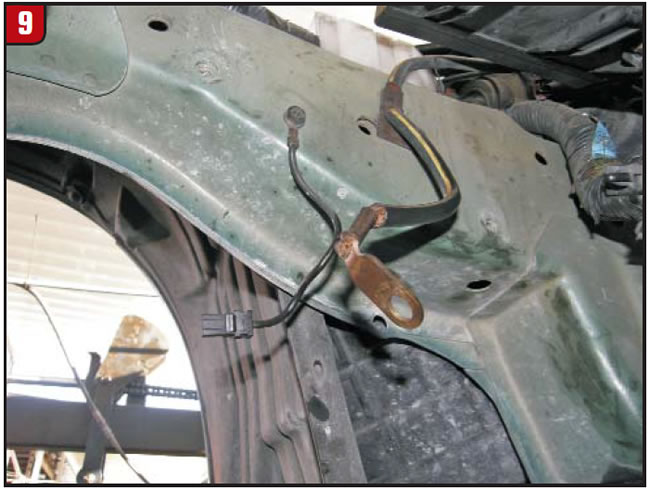
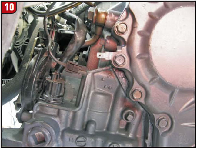
And again I say it is elusive, as I have left this wire unplugged purposely to reenact the crime and could never get it to set any codes. From the few times I have handled this on the phone lines, the main ground wire was cleaned, in addition to this wire being plugged in, resolving the problem. So it may be the combination of a poor main ground and the backup ground left unplugged causing these intermittent codes. Either way, it’s another lesson on the importance of grounds.


