
Shift Pointers
- Author: Pete Luban, ATSG Technical Supervisor
Mitsubishi F4A42/F4A51 Valve-Body Function and Problems
The F4A42 hit the streets in 1997 in the Mitsubishi Mirage. Since then it has grown into a F4A51 and has found its way into larger Mitsubishi models as well as Hyundai vehicles. This month we’re going to explore some valve-body-related issues, look at valves that can be installed incorrectly and provide some explanations about valve function.
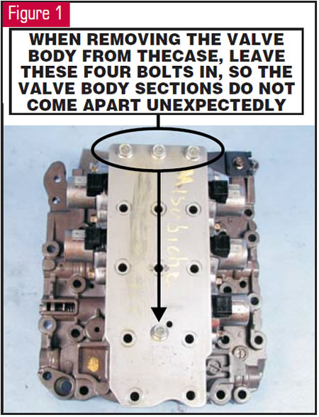
Let’s begin with removing the valve body from the transmission. Do not remove the four bolts shown in Figure 1 when removing the valve body from the transmission. if you do, you will be searching for some springs and checkballs. Remove these bolts after the valve body is out of the transmission and you are ready to disassemble it for service.
In the top of the valve body are two large steel checkballs (see Figure 2). These can get away from you easily, because the only thing keeping them in the countersunk holes is gravity. These checkballs allow air to exhaust from the transmission fluid when a clutch releases. You will notice that the drums and pistons do not contain little checkballs.
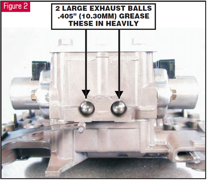
When installing the valve body, grease these checkballs in heavily, because you will be tipping the valve body to get the manual valve hooked into the linkage. In addition to this, you’ll be fighting the detent spring.
Now let’s get to the small internal parts. Figure 3 shows the lower valve body, case side, with the large spacer plate removed. As you can see, there are two spring-loaded steel checkballs. The checkball on the light spring is a reverse-clutch orifice valve and can cause harsh reverse engagement if misplaced or left out. There is also a spring-loaded plastic low/reverse-clutch accumulator valve that has a Teflon® ring (see Figure 4).
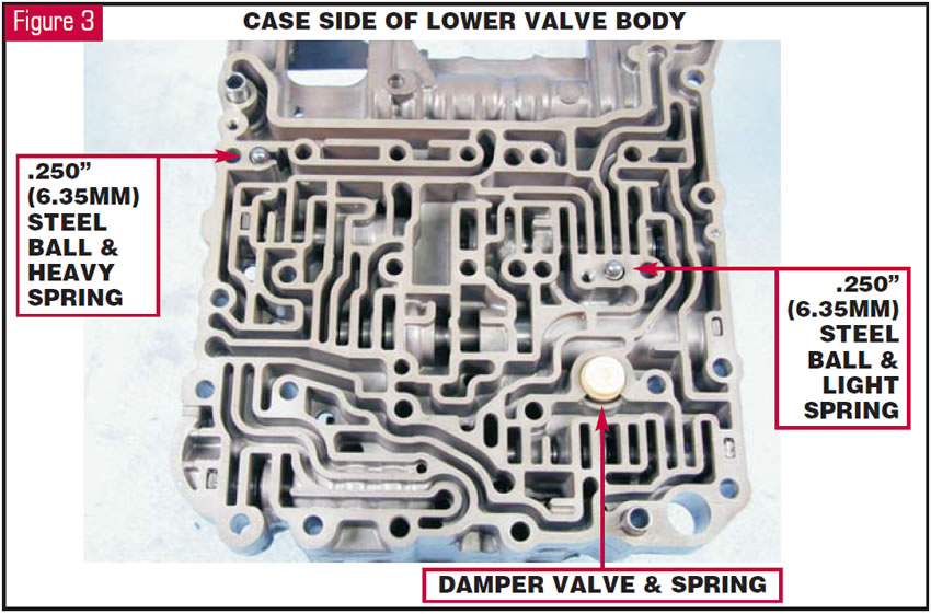
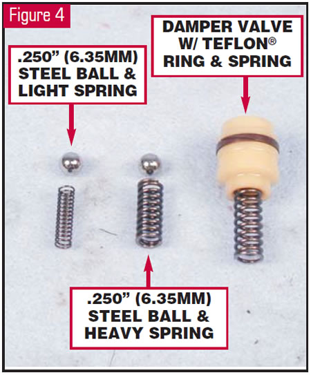
This accumulator valve is used only for reverse engagement. Should it be installed incorrectly, you will have a harsh reverse engagement. If you leave it out (you probably guessed it), there will be no reverse.
Now, we’re going to turn the lower valve body around and remove the upper valve body from it. Figure 5 shows the two spring-loaded checkballs and the one in the bathtub. The two light springs that you will find here are the same as the light spring on the other side of this valve-body section. By the way, all the small checkballs are 0.250 inch (6.35mm).
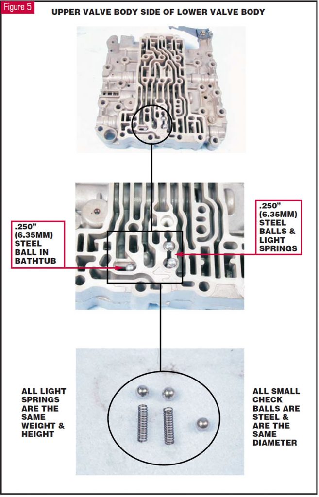
The checkball in the bathtub is a low/reverse shuttle ball and has been known to beat up the spacer plate. The spring-loaded checkball closest to the bottom of the valve body is the underdrive-clutch exhaust ball. The spring-loaded checkball directly above it is the overdrive clutch exhaust ball.
OK, that takes care of the small stuff. Now, let’s get to the valves that are contained in the lower valve body. You can follow along here with Figure 6. The lower valve body contains the manual valve. You may as well take that out first before it falls out on its own.
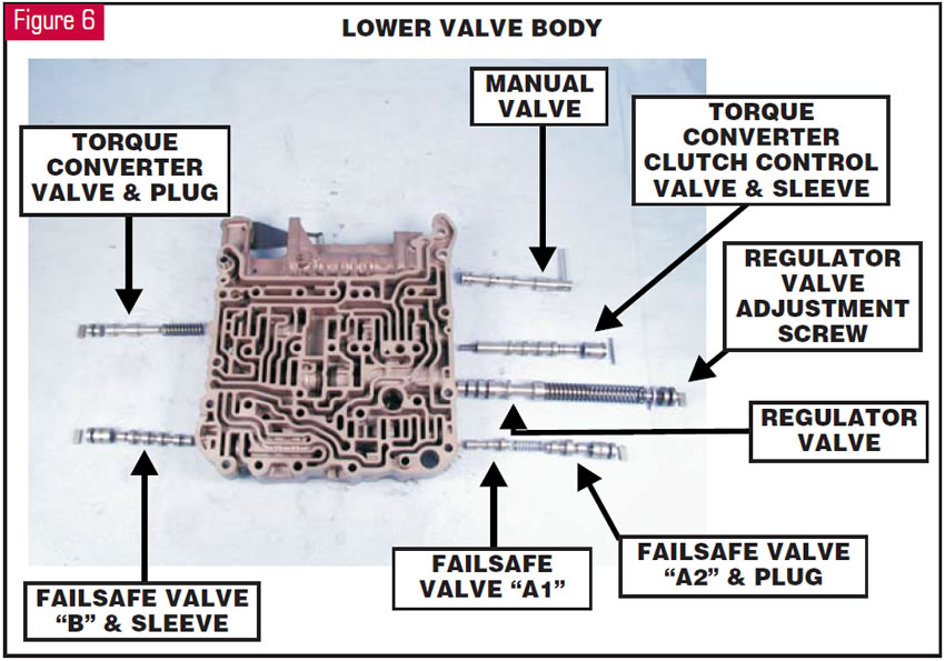
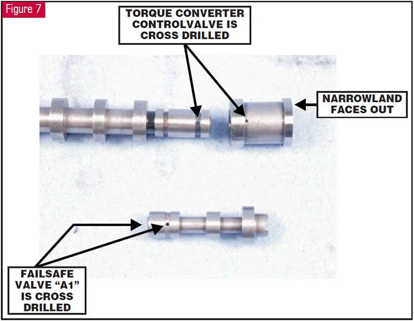
Below the manual valve is the torque-converter control valve and sleeve. This valve is cross drilled; therefore, it will require extra care in cleaning out the cross-drilled passage. You can see this more easily in Figure 7, along with the valve sleeve, which has a narrow land, also shown in Figure 7. The narrow land must face out toward the retaining pin. If the sleeve is installed backward, the converter clutch may apply momentarily, stalling the engine, when the transmission is shifted to reverse or drive from park or neutral.
OK, back to Figure 6. The next valve down is the main line-pressure regulator valve. This valve has an adjustment screw at the outer end of the valve line-up. Adjusting this screw clockwise lowers pressure. Adjusting it counterclockwise raises pressure. About one turn of this screw is equal to about 5 psi. The bottom valve line-up is failsafe valves A1 and A2. These failsafe valves are responsible for preventing a bind-up condition due to multiple clutch application when the TCM turns off all the solenoids for limp mode, which is 4th gear.
The A1 failsafe valve is cross drilled, as shown in Figure 7. These failsafe valves prevent the low/reverse clutch from applying in limp mode.
OK, back to Figure 6 again (last time, I promise). The bottom valve on the left is failsafe valve B. This valve prevents the second brake from applying in limp mode.
The top valve on the left is the torque-converter pressure-control valve, which limits the internal converter pressure. Be careful – this valve can be installed backward. Let me know what happens.
If one of these vehicles comes in on the hook with a complaint of no movement, and the owner tells you he got stuck in the snow, see whether this valve is stuck. When it sticks, it will allow the torque converter to empty.
It’s time to take on the upper valve body. You may as well get figures 8 and 9 in front of you. The upper valve body contains the five solenoids. All the solenoids are exactly the same and operate identically, and they are totally interchangeable.
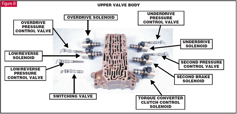
Each solenoid in Figure 8, except the torque-converter-clutch solenoid, has its own clutch pressure-control valve to control actual clutch-application feel, just like a 604. However, they are not all the same. The low/reverse-clutch pressure-control valves are cross drilled and have six spools. The second-brake and overdrive-clutch pressure-control valves are not cross drilled and have five spools, as shown in Figure 9.
Also notice that the overdrive-clutch pressure-control valve in Figure 9 shows signs of scoring on the spools. Switching these valves around will cause harsh engagements or shifts, or flared shifts, depending upon which valve bore they end up in.
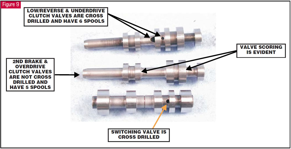
The last valve in the upper valve body is the switching valve, which also is cross drilled (see Figure 9). The switching valve is used to reduce line pressure in third and fourth gears. It also is used in failsafe to prevent line pressure from applying the low/reverse clutch when the low/reverse solenoid is turned off.
Well, there you have it – everything I know or could find out about this valve body’s operation. If you run into some weird problem that I haven’t covered here, I’d appreciate knowing about it.
Thanks to Nuttman Inc. for all the info that helped put this article together and without which it would have been incredibly difficult.


