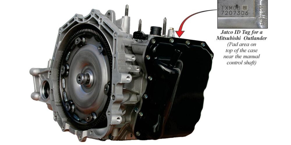
For those working on the Jatco JR613E transmission, a widespread transmission with plenty of applications, the following should be a helpful guide.
Domestic and international applications for the JF613E (also known as the RE6F01A, F6AJA / W6AJA, AJO) are as follows:
Auto Model Year Engine
MITSUBISHI LANCER 08– L4 1.8L 2.0L
MITSUBISHI OUTLANDER 07– L4 2.4L V6 3.0L
NISSAN / DATSUN MURANO 10– L4 2.5L
NISSAN / DATSUN PATHFINDER 11– V6 3.5L
NISSAN / DATSUN QASHQAI/ + 2 06– L4 2.0L
NISSAN / DATSUN X-TRAIL 07– L4 2.0L
RENAULT ESPACE 07– L4 2.0L
RENAULT KOLEOS 08– L4 2.0L
RENAULT LAGUNA 07– L4 2.0L V6 3.0L 3.5L
RENAULT MEGANE 08– L4 2.0L
RENAULT SCENIC 06– L4 2.0L
SAMSUNG SM5 09– L4 2.0L V6 2.
SAMSUNG SM7 10– V6 2.5L 3.5L
There are nine valve body attaching bolts that are two different sizes in length. Figure 2 provides their locations.
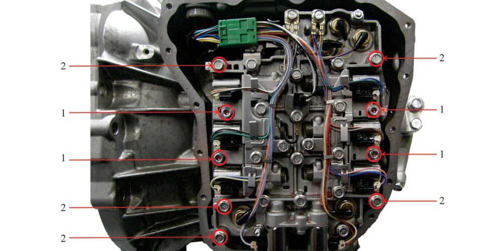
Figure 2
1 – Remove (4) 5mm hexagon socket head bolts*. Shank length: 58mm (2.28 in.)
2 – Remove (5) 10mm hexagon head bolts*. Shank length: 71.5mm (2.82 in.)
* Tighten both bolts labeled 1 and 2 to 7.9Nm (70 inch pounds)
Refer to figure 3 for small parts location in the center valve body.
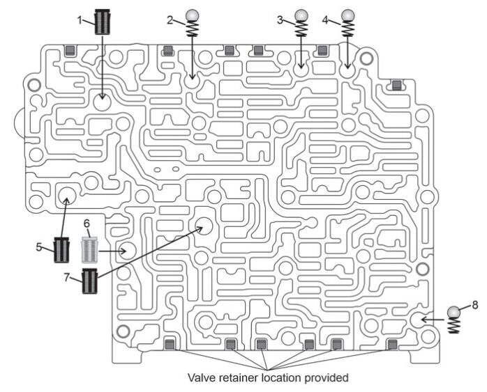
Figure 3
Figure 3 Center Valve Body Small Parts Legend
1. Filter for D range main line pressure supply to VB.
2. L/R Brake pre-fill/exhaust check ball (8mm-.312″) [M1]
3. Low clutch pre-fill/exhaust check ball (8mm-.312″)
4. High Clutch pre-fill/exhaust check ball (8mm-.312″)
5. Filter for R range main line pressure supply to VB.
6. Filter for pilot valve pressure
7. Filter for regulated main line pump pressure to LR/B control valve
8. 3-5-R clutch pre-fill/exhaust check ball (8mm-.312″)
All Check Ball Barrel Springs:
- 9mm (.355″) in length
- 0.25mm (0.010″) in wire diameter
- 5 coils
Line Pressure Relief Spring for ball 12:
- 17mm (.673″) in length
- 8mm (.316″) in spring diameter
- 1.1mm (.045″) in wire diameter
- 9 coils
Refer to Figure 4 for the inner valve body small parts location.
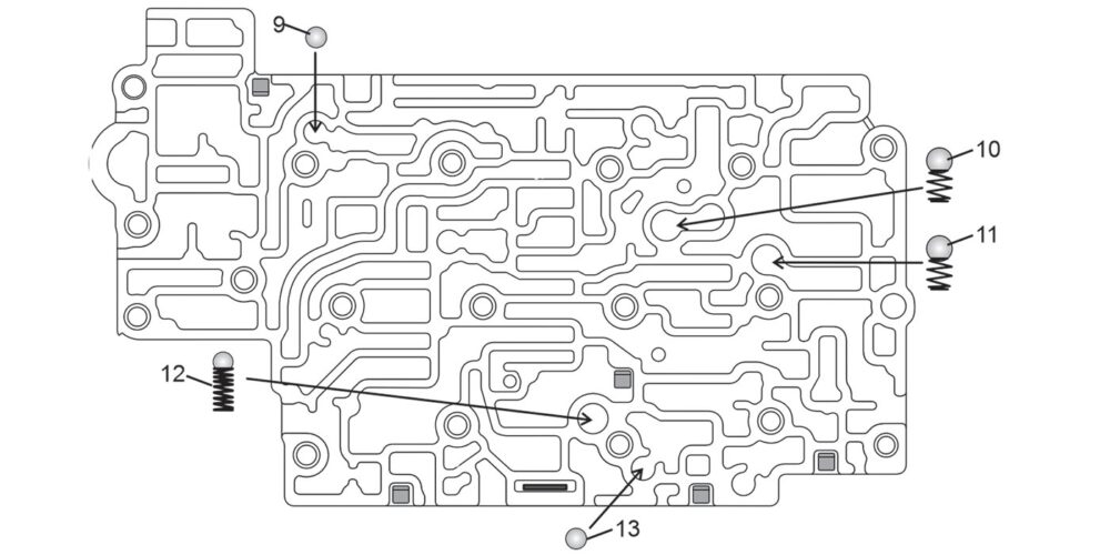
Figure 4 Inner Valve Body Small Parts Legend
9. Drive pressure exhaust control ball (5.5mm-.218″)
10. Center lube check ball (8mm-.312″)
11. Converter charge check ball (8mm-.312″)
12. Line pressure relief ball (8mm-.312″)
13. Reverse pressure exhaust control ball (5.5mm-.218″)
Refer to Figures 5 and 6 for center valve body valve and spring function and locations.
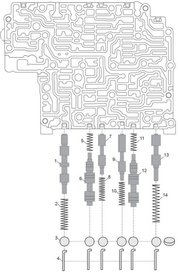
Figure 5 Legend
1. Lock-up Solenoid Shift Valve 2. 33mm x 8mm x 0.7mm x 14 coils (1.298″ x .310″ x .027″)
3. Bore plug
4. Retainer
5. 18mm x 6.9mm x 0.56mm x 8 coils (.714″ x .271″ x .022″)
6. Low/Reverse Brake Control Valve
7. Low/Reverse Brake Shift Valve
8. 25mm x 7mm x 0.66mm x 12 coils (.975″ x .265″ x .026″)
9. 3-5-R Clutch Shuttle Valve
10. 25mm x 7mm x 0.66mm x 12 coils (.975″ x .265″ x .026″)
11. 18mm x 6.9mm x 0.56mm x 8 coils (.714″ x .271″ x .022″)
12. 3-5-R Clutch Control Valve
13. 3-5-R Clutch Stall Valve
14. 40mm x 8.55mm x 0.9mm x 14 coils (1.582″ x .336″ x .036″)
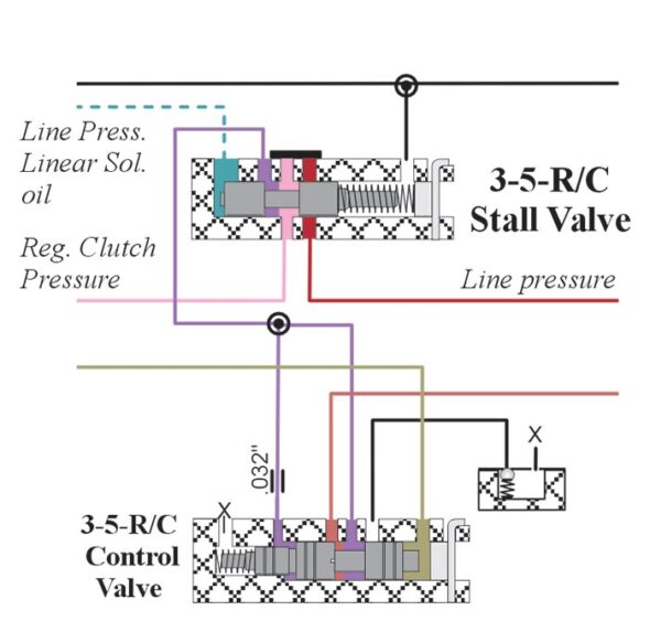
The 3-5-R Clutch Stall Valve supplies regulated clutch pressure to the 3-5-R clutch for engagement. As the throttle is depressed, line pressure linear solenoid oil moves the stall valve to the right allowing full line pressure to enter the circuit for increased holding pressure on the clutch.
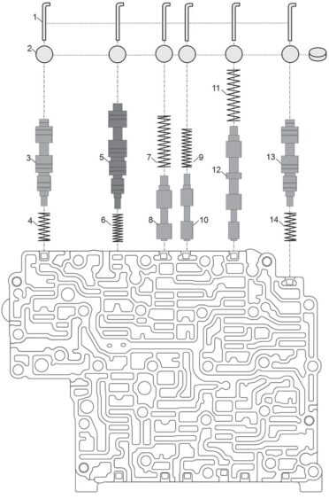
Figure 6 legend
1. Retainer
2. Bore Plug
3. 2/6 Brake Control Valve
4. 18.3mm x 7.6mm x 0.64mm x 8 coils (.720″ x .298″ x .025″)
5. Low Clutch Control Valve
6. 18mm x 7mm x 0.64mm x 11 coils (.705″ x .270″ x .025″)
7. 33mm x 8.6mm x 0.64mm x 13 coils (1.305″ x .340″ x .025″)
8. Low Clutch Shift Valve
9. 25mm x 6.7mm x 0.66mm x 12 coils (.975″ x .265″ x .026″)
10. Low Clutch Failsafe Valve
11. 33mm x 8.6mm x 0.56mm x 11 coils (1.295″ x .340″ x .022″)
12. High Clutch Hold Valve
13. High Clutch Control Valve
14. 18.3mm x 7.6mm x 0.64mm x 8 coils (.720″ x .298″ x .025″)
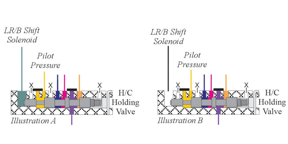
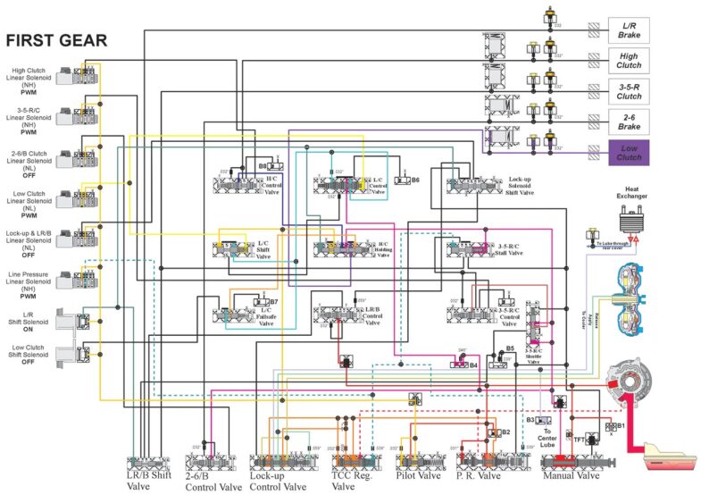
The Low-Reverse Brake Shift Solenoid turns on in Park and is on in Reverse, Neutral and Drive first gear. One of the solenoid’s function is to stroke the High Clutch “Holding” Valve (Illustration A). When the LR/B Shift Solenoid turns off as the transmission shifts to second, Pilot Pressure “holds” the High Clutch “Holding” Valve in a stroked position (Illustration B). This is done to allow for a high gear (5th gear) failsafe (all solenoids off).
Refer to Figures 7 and 8 for inner valve body valve and spring function and location.
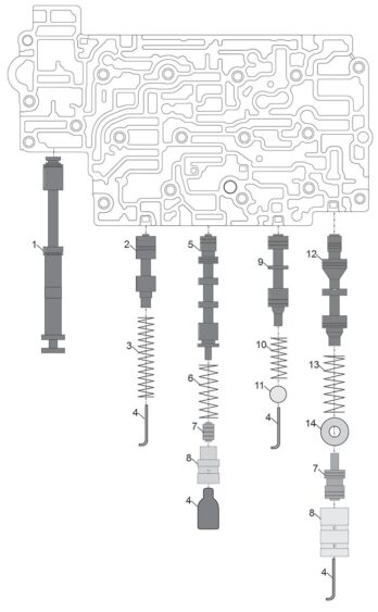
Figure 7 legend
1. Manual Valve
2. Pilot Valve
3. 49mm x 11mm x 1.4mm x 14 coils (1.935″ x .431″ x .055″)
4. Retainer
5. Lock-up Control Valve
6. 32.4mm x 12mm x 0.89mm x 8 coils (1.275″ x .475″ x .035″)
7. Boost Valve
8. Boost Valve Sleeve
9. Torque Converter Regulator Valve
10. 25mm x 10mm x 1mm x 8 coils (.995″ x .395″ x .042″)
11. Bore Plug
12. Pressure Regulator Valve
13. 38mm x 13mm x 1.12mm x 9 coils (1.406″ x .510″ x .044″)
14. Shim
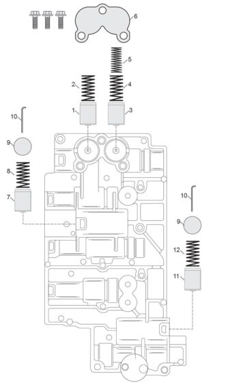
Figure 8 legend
1. 3-5-R Clutch Accumulator Piston
2. 36.3mm x 16mm x 2.4mm x 8 coils (1.430″ x .630″ x .095″)
3. High Clutch Accumulator Piston
4. 36.3mm x 16mm x 2.4mm x 8 coils (1.430″ x .630″ x .095″)
5. 36mm x 10.8mm x 1.5mm x 12 coils (1.420″ x .425″ x .060″)
6. Accumulator Cover Plate and Bolts
7. Low Clutch Accumulator Piston
8. 36.3mm x 16mm x 2.4mm x 8 coils (1.430″ x .630″ x .095″)
9. Bore Plug
10. Retainer
11. 2/6 Brake Accumulator Piston
12. 36.3mm x 16mm x 2.4mm x 8 coils (1.430″ x .630″ x .095″)
Refer to Figure 9 for solenoid location and identification.
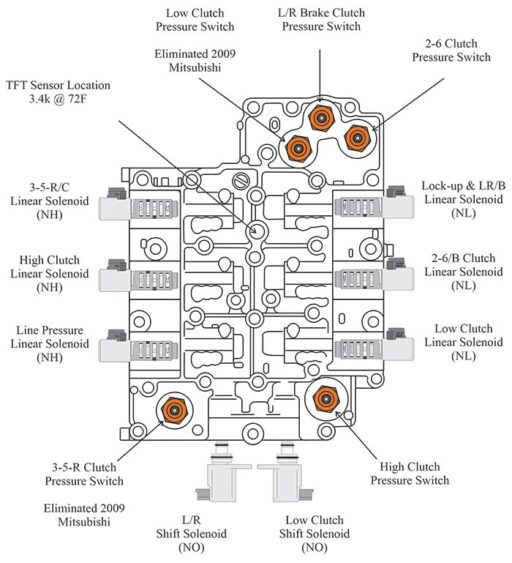
Figure 9 legend
- Linear Solenoids run at 300Hz and measure approximately 5.3 Ω at 20°C (68°F)*
- Low and L/R Shift Solenoids are on/off and measure approximately 28 Ω 5.3 ohms at 20°C (68°F)*
- Pressure switches close at approximately 10-15 psi.
* Specifications provided by Mitsubishi
Refer to Figure 10 for Mitsubishi terminal location and identification.
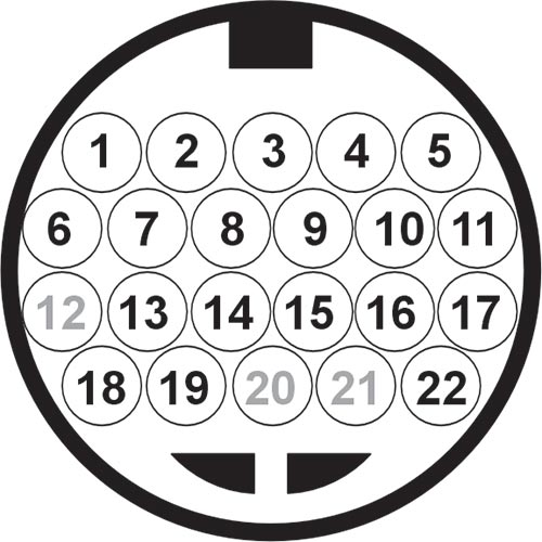
Figure 10 legend
1. Low Clutch Linear Solenoid (NL): 5.3Ω at 20°C (68°F)
2. TFT +
3. TFT – : @ 10°C (50°F) 6.62k Ω
3. TFT – : @ 25°C (77°F) 3.51k Ω [Approx. 2.35V]
3. TFT – : @ 80°C (176°F) 0.55k Ω [Approx. 0.69V]
3. TFT – : @ 110°C (230°F) 0.25k Ω
4. Lock-up & Low-Reverse Brake Linear Solenoid Valve (NL): 5.3Ω at 20°C (68°F)
5. High Clutch Pressure Switch: Closes at approximately 10-15 psi
6. 2-6 Brake Linear Solenoid Valve (NL): 5.3Ω at 20°C (68°F)
7. Low-Reverse Brake Pressure Switch: Closes at approximately 10-15 psi
8. Low Clutch Pressure Switch: Closes at approximately 10-15 psi
9. Line Pressure Linear Solenoid Valve (NH): 5.3Ω at 20°C (68°F)
10. 2-6 Brake Pressure Switch: Closes at approximately 10-15 psi
11. 3-5-R Clutch Pressure Switch: Closes at approximately 10-15 psi
12. Not used
13. Ground
14. 3-5-R Clutch Linear Solenoid Valve (NH): 5.3Ω at 20°C (68°F)
15. Not used
16. Not used
17. Low-Reverse Brake Shift Solenoid Valve (NO – On/Off): 28Ω at 20°C (68°F)
18. Not used
19. High Clutch Linear Solenoid Valve (NH): 5.3Ω at 20°C (68°F)
20. Not used
21. Not used
22. Low Clutch Shift Solenoid Valve (NO – On/Off): 28Ω at 20°C (68°F)
Refer to Figure 11 for a first gear hydraulic.