Tech to Tech
- Subject: Diagnosis of lean-condition codes
- Essential Reading: Diagnostician
- Author: Brian Manley
Memory codes create some servicing excitement
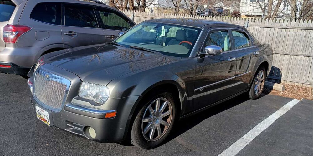
When a vehicle rolls in with its malfunction indicator lamp (MIL) illuminated (Figure 1), do you experience excitement or dread? I always get a little giddy. Why? The thrill of the unknown and the process of diagnosing always seem “fun” for me. Granted, the path is often quick and relatively easy; however, it can also become a labor-intensive task that requires time, research and patience.
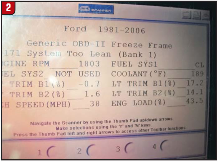
This particular vehicle gave us two codes: P0171 and P0174. It is important to note that neither of the codes was current; they appeared only under “Memory Codes.” In a situation like this, I look at freeze-frame data, and we had the following data snapshot from when the code set: vehicle speed, 38 mph; coolant temperature, 189°F; long-term fuel trim for both engine banks was at 14% and 17%; engine speed, 1,803 rpm (Figure 2).
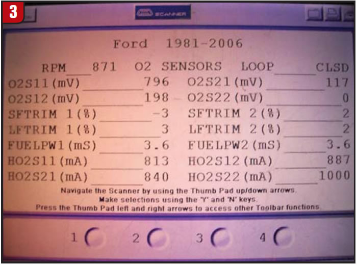
What do these numbers mean? The most-important data – the fuel-trim numbers – mean that the computer is compensating for a lean condition. In addition, because of the V-6 engine configuration, the data show a lean condition on both banks. In my experience, this usually means the engine has low fuel pressure, a dirty mass-airflow (MAF) sensor or a large vacuum leak. If the fuel-trim numbers were high on one bank and not the other, there would be a lean condition on just one side of the engine, eliminating the MAF and fuel pressure as possible causes. Because of the high fuel-trim numbers from the freeze-frame data page, I studied the live data-stream page and focused on the parameters associated with a lean condition (Figure 3). These fuel-trim numbers were much lower, but still on the “add fuel” side of 0. You may notice that HO2S22 is at 0 millivolt; this is because there is only one downstream sensor in use, which is HO2S12.
Next, I decided to grab my can of MAF-sensor cleaner and give my sensor a bath. After I did so, my fuel-trim numbers did not improve. However, I suspect that many vehicles are running around with dirty MAF sensors and can benefit from cleaning.
I decided to pull up the diagnostic information for a P0171 to aid in my diagnosis. Although I had cleared the code and the light had not returned in a few days of driving, I did not feel comfortable sending my customer away without finding a plausible root cause for the lean condition.
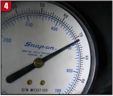
My next test was to hook up a fuel-pressure tester to check for fuel pressure. This vehicle has a mechanical, returnless system with a key on, engine off pressure listed as 55-65 psi. My gauge showed 70 psi (Figure 4), so I moved on to checking for an injector fault by scrutinizing injector data. As expected, the injector data did not show an injector fault, so I moved on to testing the injector flow rate. With my fuel-pressure gauge still hooked up, this was a simple task to energize the fuel pump for each injector and energize each one with my tester. Each one had an even drop indicating balanced flow.
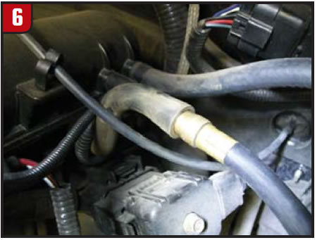
Next on deck, I decided to test the induction system for air leaks, so I pulled out my trusty smoke machine (Figure 5), pulled the vacuum hose off its PCV valve and inserted the smoke tester’s output line (Figure 6). I capped off the throttle body on the intake side and did the same to the exhaust pipe exiting out back, and then I activated the system. I have performed this test on different vehicles, so I am aware that it will reveal vacuum leaks small enough to evade a stethoscope’s ability to hear.
After repeated tests I could not find a leak of any significance, so I decided to hold the vehicle over and test the engine cold. In the past I have found leaks on a cold engine that have not shown up on warm ones.
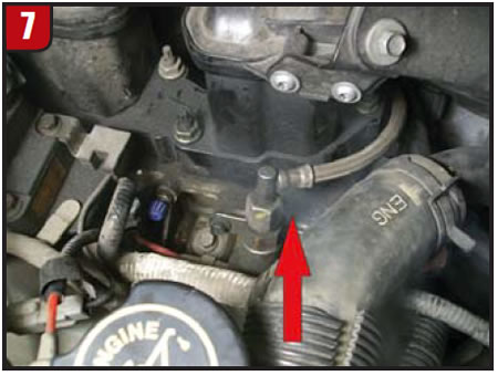
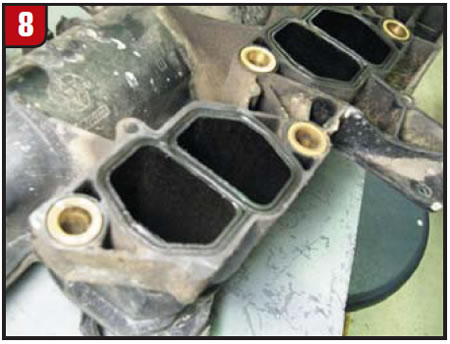
This vehicle would turn out to be just such a case when I checked for leaks on a cold engine, and smoke came pouring out from the mating surface where the upper plastic intake joins the lower aluminum intake (Figure 7). Upon disassembly, I found the rubber seals (Figure 8) to be hard as a rock. Comparing the old seals with some fresh ones revealed just how much the old ones had shrunk.
In a related tip, our customer had indicated that the “Check Engine” lamp illuminated on one of our recent below-zero winter days. I’m certain this further shrunk our seals. This made sense to me: The freeze-frame data indicated that the code set before the engine had completely warmed up.
Note to the wise: Always search technical-service bulletins (TSBs) on your information system when hunting for intermittent issues. In addition, I found many threads on the International Automotive Technicians Network (iATN) regarding this issue. Most techs found that dirty MAFs and vacuum leaks from hoses and/or the intake manifolds on these engines caused their lean-running codes.
Did the intake gaskets fix my Ford? Time will tell, and I am confident that the condition of the intake seals, coupled with their high failure rate, will combine to have been the root cause for this customer’s concern.

Brian Manley is a vocational automotive instructor for the Cherry Creek school district in Aurora, Colo. He is an ASE master certified automobile technician and a former member of the National Automotive Technicians Education Foundation (NATEF) board of trustees. You can reach him at [email protected].
This copyrighted article is reprinted with the permission of AutoInc., the official publication of the Automotive Service Association (ASA). To learn more about ASA and its commitment to independent automotive-service and repair professionals, visit www.ASAshop.org or call 800-272-7467.