Shift Pointers
- Author: Wayne Colonna
- Subject Matter: Ignition coil #2 primary circuit fault
- Issue: Crank sensor, possibly
There is no doubt in my mind that everyone person who works on cars has had cranky days. How frustrating it is when a solution to a problem cannot be found. Especially when every feasible means of diagnostics has been performed and all checks well. Such was the case with Lorenzo Ortiz from Phillips Transmissions. This is what he passed on to me to share with you all.
Lorenzo’s report
A 2003 Jeep Grand Cherokee 4.0L 4×4 comes into the shop for transmission repair. After installing a rebuilt transmission the vehicle exhibits a misfire. Upon inspection, I find the vehicle has stored a P0352 code for an ignition coil #2 primary circuit fault. So I perform the diagnostics related to this code and do not find any circuit problems.
Upon further inspection of the PCM, I discovered that when I checked the control side of the #2 ignition coil at idle, it becomes very erratic. I unplugged the alternator to see if that would make a difference and it did not. I also noticed that when the engine was revved up to 200 to 300 rpms, the PCM set codes P0351 and P0353, circuit #1 and circuit #3 ignition coil primary circuit faults. I then proceeded to double-check all PCM circuits for shorts, for good power and grounds, and everything once again checks out good. At this point I determined there must be a problem the PCM so I installed a new PCM.
After rechecking the vehicle, to my surprise, the same problems existed. I then went back through all my data on my scanner to see what I might have missed. Everything seemed good. At this point, if for no other reason than frustration, I snapped the throttle a couple times when suddenly code P0320 for the crank sensor signal set. At this point I was thinking, can it be my R&R guy, after installing more than 100 of these, could he have left the crank sensor misadjusted? Could this be what had been causing all these ignition coil circuit codes?

After checking the crank sensor, that was exactly what the problem was. Once it was properly adjusted, all the ignition coil-code settings went away. How a misadjusted crank sensor could cause these types of codes to set is still a mystery to me. That is a question for the Chrysler people to answer. It is interesting to note that when I unplugged the alternator, the PCM would not set any codes yet the engine still had a misfire.
It’s puzzling to consider how a misadjusted crank sensor could cause ignition coil circuits to set. Particularly so as the list of possible causes provided by the manufacturer does not mention the crank sensor: good trip equal to zero; (A142) ASD relay output circuit; coil rail resistance; ignition coil; ignition coil driver circuit open; ignition coil driver circuit shorted to ground; and PCM.
As a result, a simple unadjusted crank sensor caused a cranky couple of days.
I’m not sure if I can say that the moral of this case study is to remember that ignition-coil codes could be set by an out-of-adjustment CKP sensor, or to simply remember to adjust the sensor? Conclusion, I report, you decide.
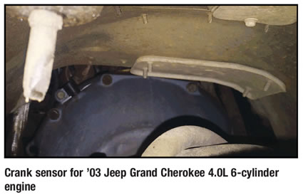
Crankshaft position sensor servicing notes
The Crankshaft Position (CKP) sensor is mounted to the transmission bell housing and is adjustable via the attaching bolt. A wire shield/router is attached to the sensor.
New replacement sensors should be equipped with a paper spacer glued to the bottom of the sensor. If installing (returning) a used sensor to vehicle, a new paper spacer must be installed to the bottom of sensor. This spacer will be ground off the first time the engine is started.
When installing a new sensor, be sure a paper spacer is glued to the bottom of the sensor. If it is missing you will need to obtain a new spacer. The part number is PN05252229. The same applies to reused sensors. Simply clean the bottom of it and peal and stick the new spacer to the bottom. The spacer measures 0.551” in diameter and 0.034” in thickness.
Installation procedure
- Install sensor into transmission bell-housing hole.
- Position sensor-wire shield to sensor.
- Push sensor against flywheel/drive plate.
- With sensor pushed against flywheel/drive plate, tighten mounting bolt to 7 Nm (60 in. lbs.) torque.
- Route sensor-wiring harness into wire shield.
- Connect sensor pigtail harness electrical connector to main wiring harness.


