Technically Speaking
- Author: Wayne Colonna
The hybrids are here, and we’re not talking about plants, folks! A partial definition of the word hybrid found in a typical Webster’s dictionary goes like this:
hybrid (hi brid) n. 1. An offspring of two animals or plants of different species, varieties, breeds etc. 2. Anything of mixed origin or unlike parts.
When it comes to hybrid vehicles here in the United States, we are talking about vehicles using gasoline engines and electrically powered motors. These are not to be confused with “The Veggie Van” fueled by vegetable oil that made headline news in the late ’90s (really!! Take a look at http://www.veggievan.org).
Honda hit the road first with its gas-engine/electric-motor combo called the Insight, but it was Toyota that pioneered the “Hi Voltage Battery” technology and used it in its Prius vehicle. Ford broke ground by producing the first hybrid SUV with its 2003 Ford Escape. Ford also has plans in the works in which it will use the latest hybrid-electric-vehicle technologies with an advanced new fuel cell to produce the zero-emissions Ford Focus. Prototypes begin in 2004. Other manufacturers soon will have vehicles of environmentally friendly design available for purchase here as well. So it’s another technology that the auto-repair and rebuilding industry needs to prepare for.
In this and following articles, I will introduce to you a bouquet of hybrid vehicles starting with the Toyota Prius. This introduction is intended to familiarize you with how it works, the proper safety procedures to follow and the type of “transmission” that is used. I will do the same with the Honda Insight and Civic vehicles. (For additional reading, a great Web site to visit is “Howstuffworks” at http://auto.howstuffworks.com/hybrid-car.htm. It does a really nice job of explaining how hybrid vehicles work).
The Toyota Hybrid System (THS) in the Prius combines the 1.5-liter, 16-valve DOHC gasoline engine (the INZ-FXE) and electrical power source to drive the front wheels. Each of these power sources can supply power to the front wheels independently or in conjunction with one another. This type of arrangement is known as a parallel hybrid powertrain.
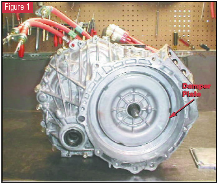
The transmission in this vehicle is called the “P111 Hybrid Transaxle” (see Figure 1), otherwise known as the “Power Split Device,” which is ingeniously designed to allow both power sources to work together or independently. It also performs other functions, but I am getting ahead of myself. Let’s start by explaining a little about the electrical-power source, beginning with the hybrid-vehicle (HV) battery.
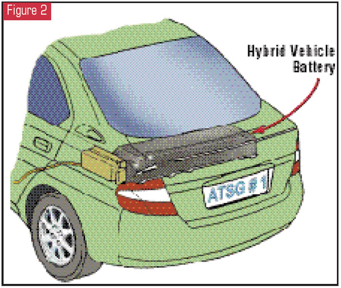
The HV battery consists of 228 1.2-volt nickel-metal-hydride batteries placed in “six-pack modules.” Thirty-eight modules divided into two holders then are connected in series to obtain a whopping 273.6 volts DC. This battery-pack assembly is tightly contained and is in the trunk area behind the rear seat (see Figure 2). It has its own electronic control unit that monitors the batteries’ state of charge and executes charging commands when needed.
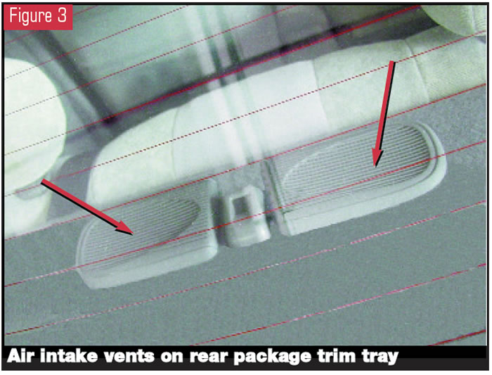
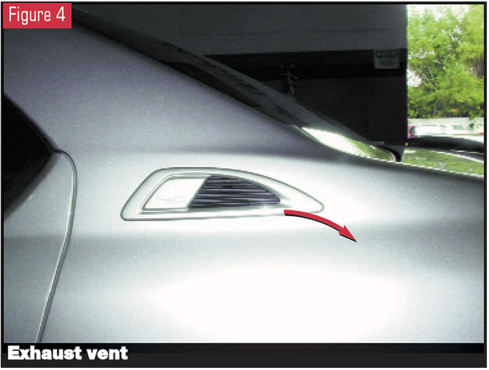
The battery ECU also monitors the batteries’ temperature. When needed, the battery ECU will control a cooling fan from off to LO, MID and HI speeds. Priority is given to the air conditioner and will keep the fan off or LO during marginal battery temperatures. Note: The air intake for these batteries is mounted on the rear package trim tray as shown in Figure 3. The heat is exhausted through a vent mounted on the driver-side body exterior (see Figure 4). Should an object such as clothing be placed over the intake vents on the package trim tray, the batteries may not cool properly, which could cause the output-control warning light to illuminate.
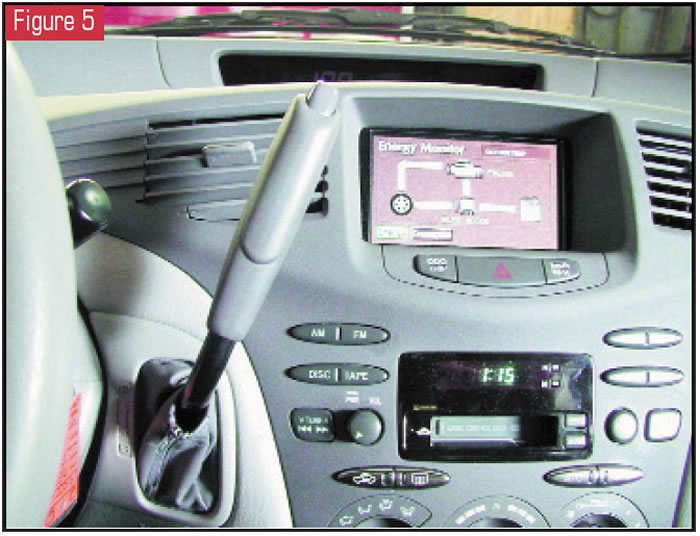
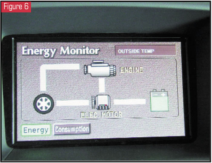
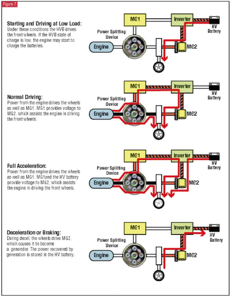
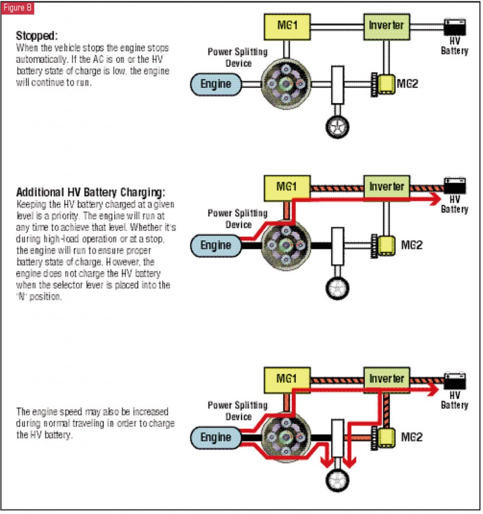
This powerful battery pack drives the front wheels during startup and low-load take-offs. It also assists the engine in driving the front wheels during full-acceleration conditions. In the dash panel of the vehicle there is an information screen (also known as the energy-monitoring screen) that displays to the driver whether the four-cylinder engine, the electric motor or both are driving the front wheels (see figures 5 and 6). The electric motor displayed in the information screen connecting to the HV battery is called “motor generator 2.” You might be asking yourself, “If there is a motor generator 2 (MG2), there must be a motor generator 1 (MG1). And you are right – there is. Figures 7 and 8 briefly illustrate the MG1 and MG2 with the inverter throughout the different stages of the THS.
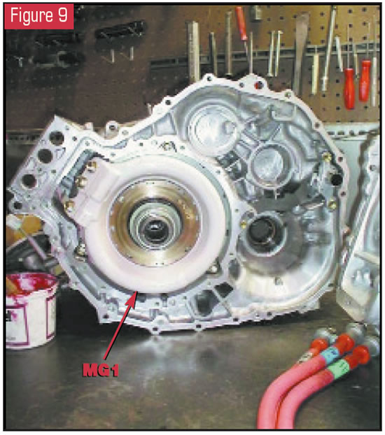
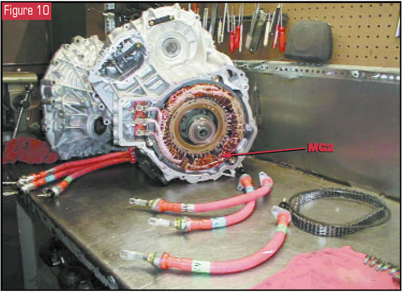
These motor generators are compact, lightweight and highly efficient alternating-current permanent-magnet synchronous type. This means that they produce AC voltage with a waveform that is in sync with the mechanical input or output. These generators are inside the P111 hybrid transaxle at opposite ends, as you can see in Figures 9 and 10.
The MG1 is a constant generator with one exception: It is connected to the sun gear, which allows it to function as a starter for the engine. Otherwise, its job is to recharge the HV battery and supply electrical power to MG2.
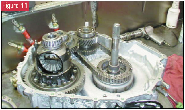
The MG2 is mechanically splined to the planetary ring gear, where a chain connects the ring gear to a countergear set used to drive the differential (see Figure 11). This allows the MG2 to act as a motor, helping the engine supply power to the front wheels. During off-throttle coast or braking, the MG2 acts as a generator that stores voltage in the HV battery and can help slow the car.
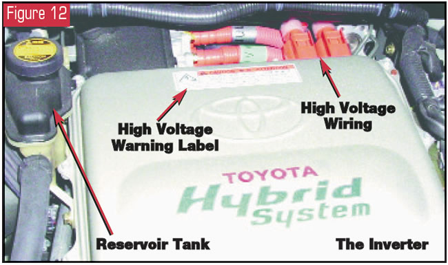
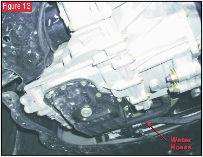
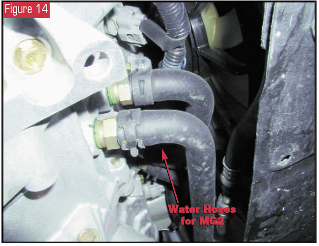
The hybrid vehicle’s on-board computer system, called the “HV ECU,” controls the different functions the motor generators can perform through a device called the inverter (see Figure 12). Next month’s article will provide further explanation of the operation of the motor generators and the inverter. But for now, these devices are high-voltage items and produce enough heat that they need a cooling system. In Figure 12 you will notice that to the left of the inverter is a water reservoir. This is an independent “water-pump-powered” cooling system for the inverter and the two generators. This explains why you will see water hoses going into the transaxle. Figures 13 and 14 give you a view of the hoses going to MG2 for cooling.
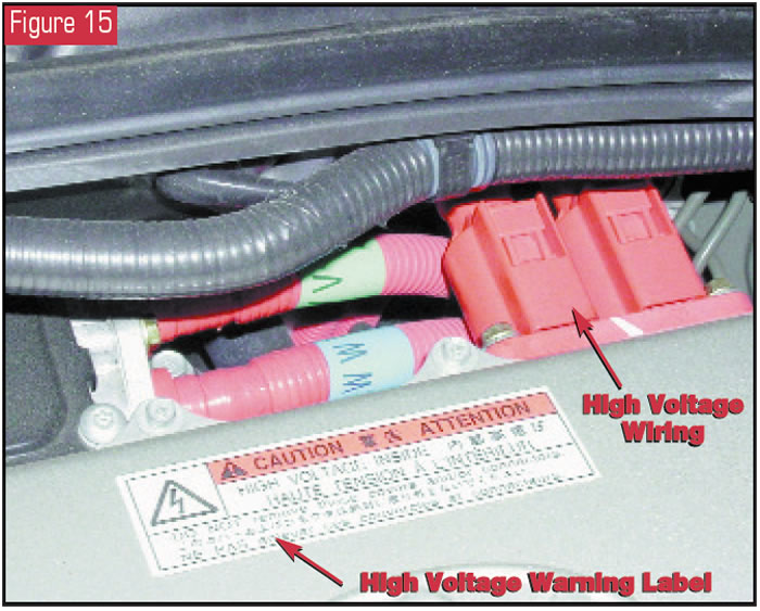
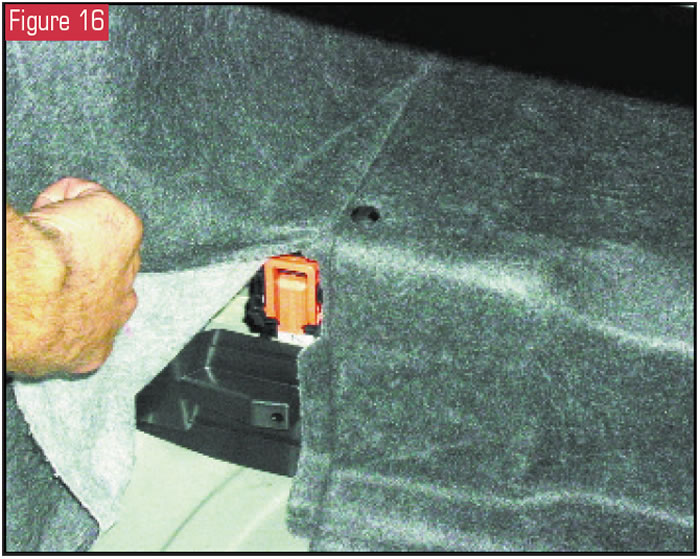
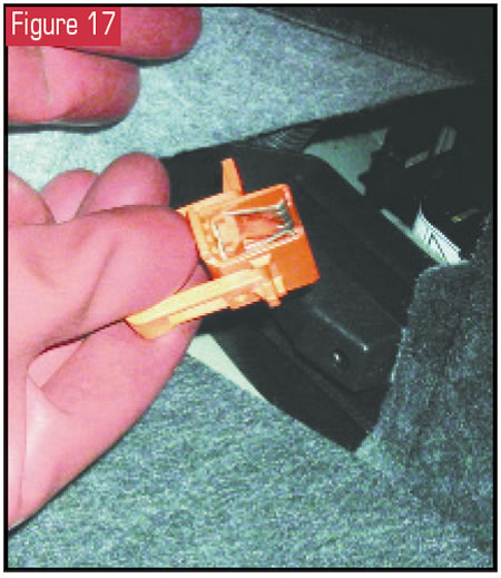
The warning label on the inverter (Figure 15) is not something to ignore. Here is where several safety tips MUST be employed to service these vehicles properly. As Figure 15 points out, all high-voltage wires are encased in bright-orange conduit for easy identification. This system must be powered down before any work is performed. To do this, locate the service plug in the trunk area under the carpet near the left side of the rear seat (see Figure 16). With a pair of lineman’s gloves, remove this service plug as shown in Figure 17. This will open the HV battery circuit from the electrical system. Wait 15 minutes to allow time for the system to fully discharge before commencing any work.
Two more very important notes: Remember that the MG2 is mechanically connected to the front wheels. This means that if the P111 transaxle is still in the vehicle, pushing the car will generate electricity into the system, regardless of the removal of the service plug. Second, if you have been medically treated with a pacemaker, NEVER pick up a generator from an opened P111 transaxle and hold it close to your body.
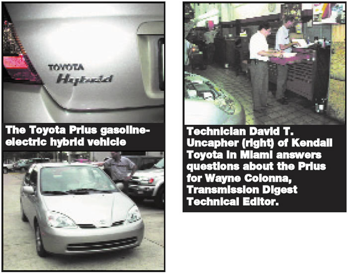
Special thanks to Toyota and to David T. Uncapher. David, a Master Diagnostic Technician for Kendall Toyota in Miami, took the time in July 2002 to show Peter and me the Prius, let us take pictures and answer the many questions we had for this article.
Special thanks also to Frank Kuperman from Phoenix Remanufactured Trans. He supplied us with the photos we needed of the hybrid P111 transaxle to make this and next month’s articles possible. So, thanks for your patience, David; we needed to wait for these transaxle pictures.