
Shift Pointers
- Author: Pete Luban, ATSG Technical Supervisor
We have had some confusion on the ATSG help lines in reference to 1999 and later Mitsubishi Fuso tilt-cab medium-duty trucks equipped with the Aisin Seiki.
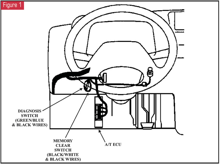
The first problem is, how do I get codes out of these trucks? Since aftermarket scan tools do not communicate with these trucks, data is not available and code retrieval must be done via the flash-code method. That means that a certain procedure must be performed, after which a light somewhere on the dash will flash a code pattern. The illustration in Figure 1 shows the locations of the diagnosis switch and the memory-clear switch, both of which are single-pin connectors.
To retrieve current codes:
- Turn the ignition on.
- Disconnect the diagnosis switch. The diagnosis-switch connector will have a green/blue wire on one side of the connector and a black wire on the other side.
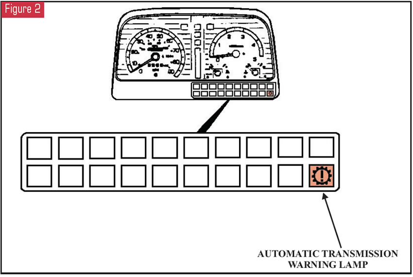
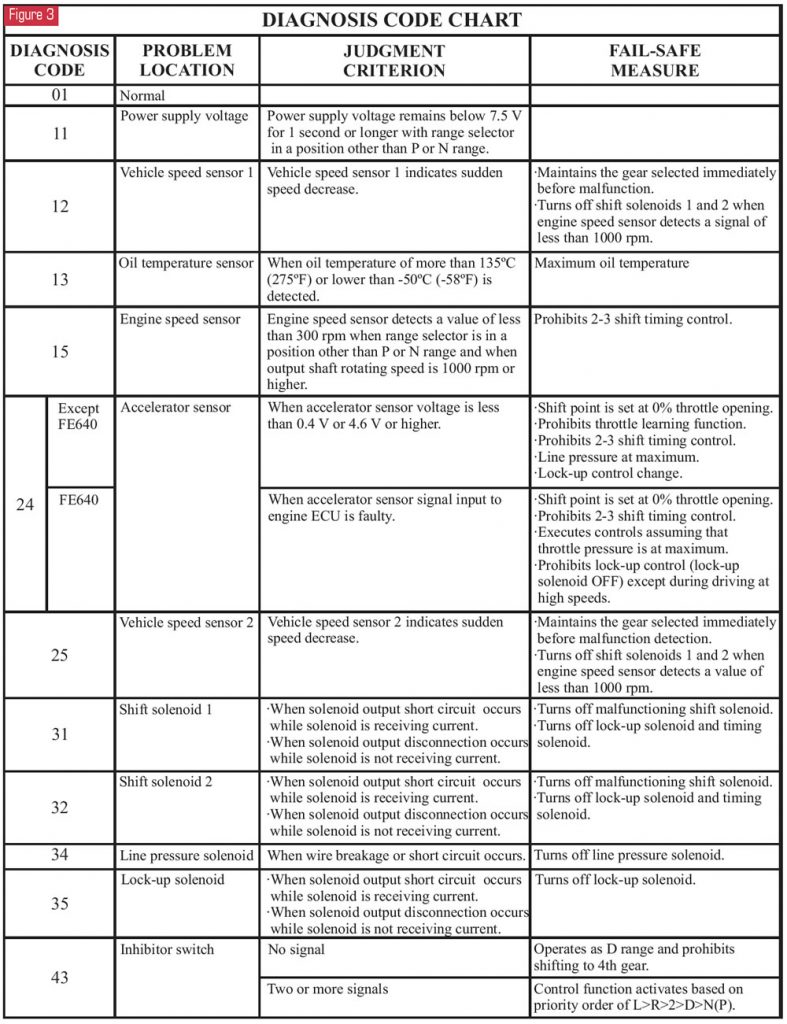
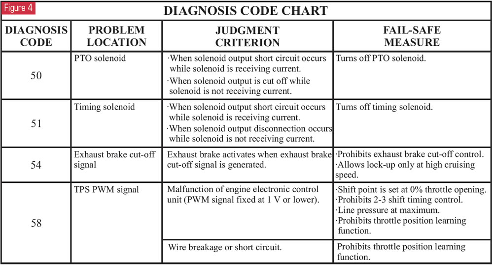
- Watch the warning lamp below the instrument cluster shown in Figure 2 for the flash-code pattern, and refer to the code charts in figures 3 and 4.
To retrieve current and historical codes:
- Turn the ignition on.
- Disconnect the connectors for the diagnosis switch and the memory-clear switch. The memory-clear switch will have a black/white wire on one side of the connector and a black wire on the other side.
- Watch the warning lamp below the instrument cluster shown in Figure 2 for the flash-code patterns, and refer to the code charts in figures 3 and 4.
To read diagnostic codes:
- The warning lamp will come on for 2.4 seconds when the ignition is turned on and will then turn off.
- The flash for the “10s” digit is 1.2 seconds long, and the flash for the “ones” digit is 0.4 seconds long. The flashes for the “10s” and “ones” digits are separated by 0.6 seconds.
- There is a 2.4-second lamp-off period between codes. Figure 5 illustrates code timing.
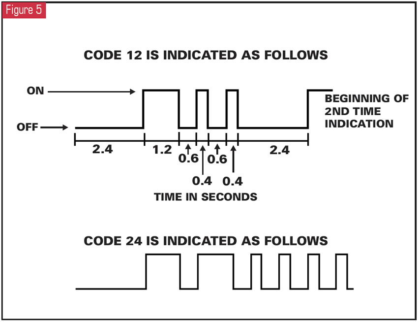
If more than one code is stored, they will be displayed in numerical order starting with the lowest.
Important Note: Each code is displayed three times before the next code appears.
After all codes have been displayed, the process will repeat itself.
To clear codes:
- Keep the diagnosis-switch connector connected.
- Turn the ignition on.
- Disconnect the connector for the memory-clear switch. After more than one second, reconnect the memory-clear switch. After three seconds, all codes will be cleared.
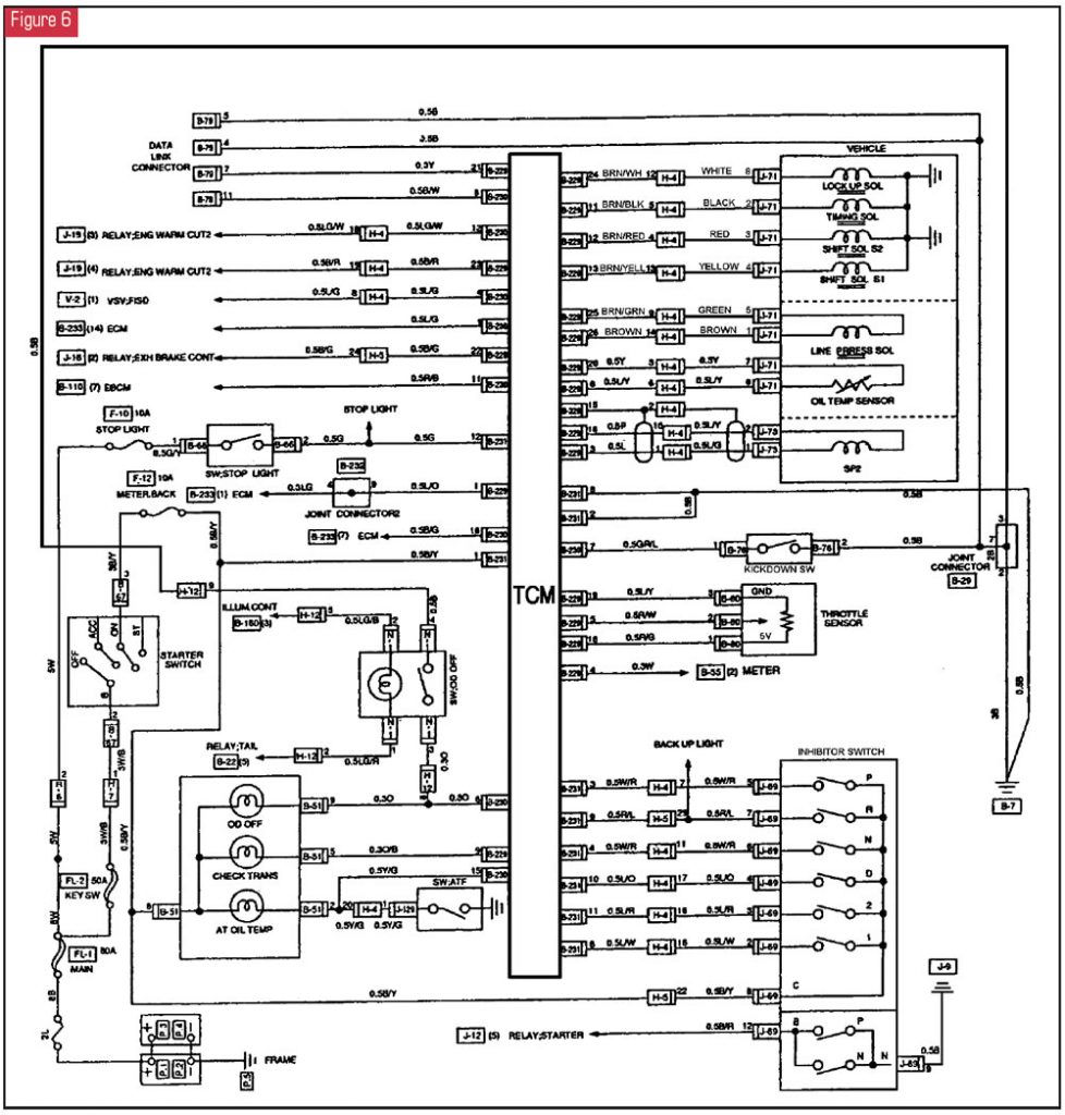
The second problem is wire-color identification for the transmission solenoids. The wires from the transmission to the cab-to-chassis connector are solid colors. Most wire diagrams, including the factory wire diagrams, show these wires as multi-colored. The wire diagram in Figure 6 shows the correct wire colors at the transmission.
I hope this info saves you some time and confusion.


