Shift Pointers
- Subject: Internal components and operation
- Unit: eCVT transaxle
- Vehicle Applications: Ford Escape, Mercury Mariner & Mazda Tribute hybrids
- Essential Reading: Rebuilder, Diagnostician
- Author: Pete Luban, ATSG
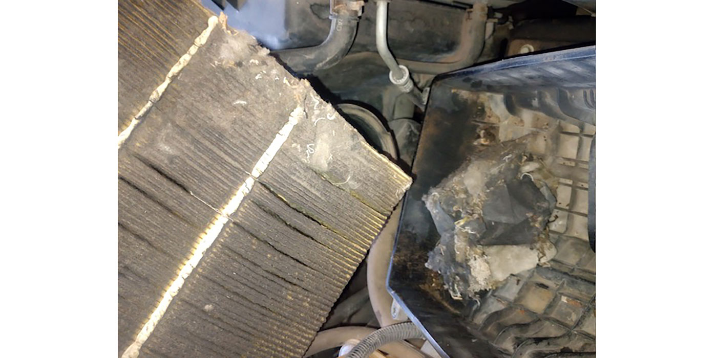
In part 1 of this article last month we ended with the transaxle sitting on the bench awaiting disassembly, so let’s disassemble. You will notice in Figure 1 that we are ready to remove the top pan; we can’t call it a valve-body cover because there is no valve body.
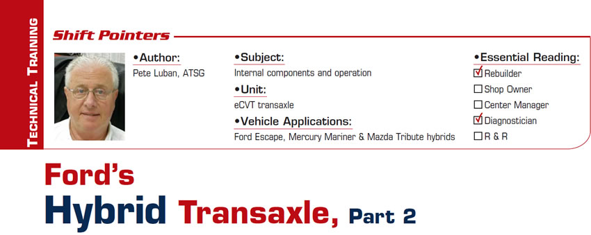
You’ll also notice that there is damage to this pan. This transaxle weighs almost 300 pounds, so you really want to avoid this kind of damage during removal and handling of the unit because of what’s under this cover (Figure 2). That circuit board, which is the control for the transaxle internal computers, could also be damaged.
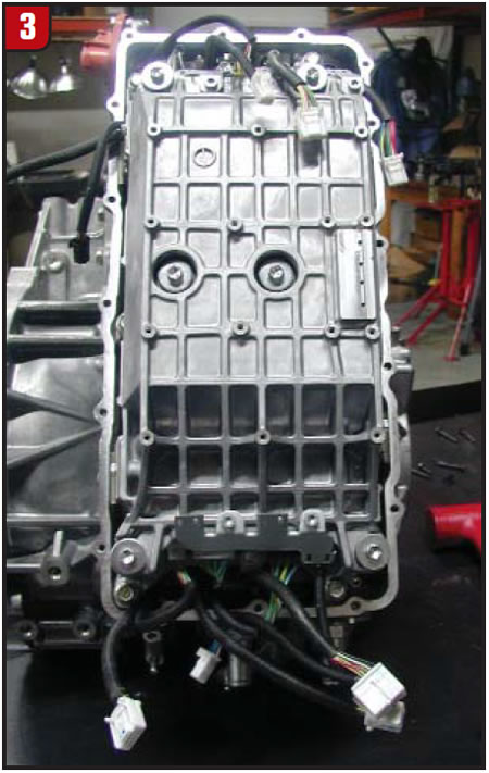
Exercise care when handling this circuit board so it doesn’t get damaged, and also be mindful of static-electricity discharge. Once the circuit board has been removed the condenser cover is next (Figure 3).
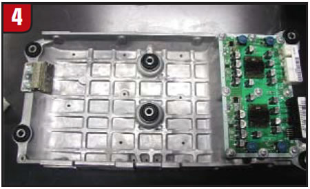
Here again exercise care, because there is electronic circuitry on the underside of this cover (Figure 4). Also in Figure 4 you will notice a mesh ground strap; there are five of those to disconnect, and this would be a good time to do that.
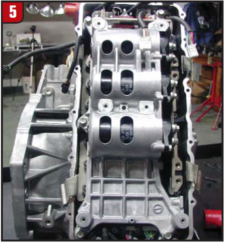
Once the condenser cover is removed the three high-voltage condensers are exposed (Figure 5) and should be safe to handle at this point.
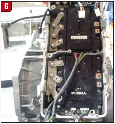
Removal of the condenser housing will allow access to the internal power units (IPUs), and there are two of those (Figure 6). One is rated at 300 amps and controls motor/generator 1; the other is rated at 600 amps and controls motor/generator 2.
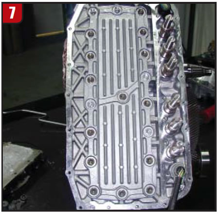
Once the condenser housing is removed an aluminum plate bolted to the transaxle case is visible (Figure 7); this plate seals the transaxle cooling chambers and really does not need to be removed.
In Figure 8 you can see the transaxle temperature sensor between the coolant-hose fittings.
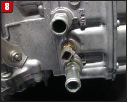
The dedicated transaxle cooling system is made up of an electric pump, separate radiator, a Degas bottle from which the system is filled, and the necessary hoses and fittings. There is no thermostat in the system, so flow is constant cold or hot.
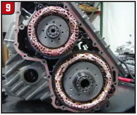
Now for the internal parts. In Figure 9 the rear cover has been removed, exposing motor/generators 1 and 2. Disconnect the three-phase connections on both motors as well as the three bolts that hold each in place, and pull them straight out. Removing and installing these motors is a little tricky because of their tight fit in the case, so the idea is to try not to cock them. They are heavy as well, so watch your fingers and be sure to check the motor-support bearings; they support quite a bit of weight.
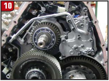
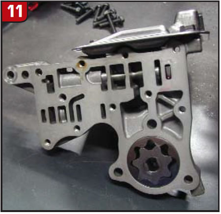
In Figure 10 the bellhousing has been removed, allowing access to all the toothed components as well as the lubrication pump and sump filter. This pump is a gerotor style (Figure 11) and is for lubrication purposes only.
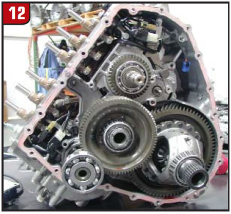
In Figure 12 you can see all the final-drive components as well as the location of the power-split device. This is similar to the Toyota Prius design. Unlike the Prius the eCVT does not use a drive chain; it is gear-to-gear driven. The lubrication-pump drive is engine driven from the input carrier. Like the one in the Prius, the transaxle does not use a torque converter; instead, it uses a damper assembly containing a clutch that will slip briefly to eliminate vibration.
Despite the size of this unit there are not a whole lot of parts and pieces in it, so it’s a relatively simple unit to work on.
With 1.25 million hybrid vehicles on the road right now and a million or so more coming within the next few years, there will be plenty of them that will need repairs.