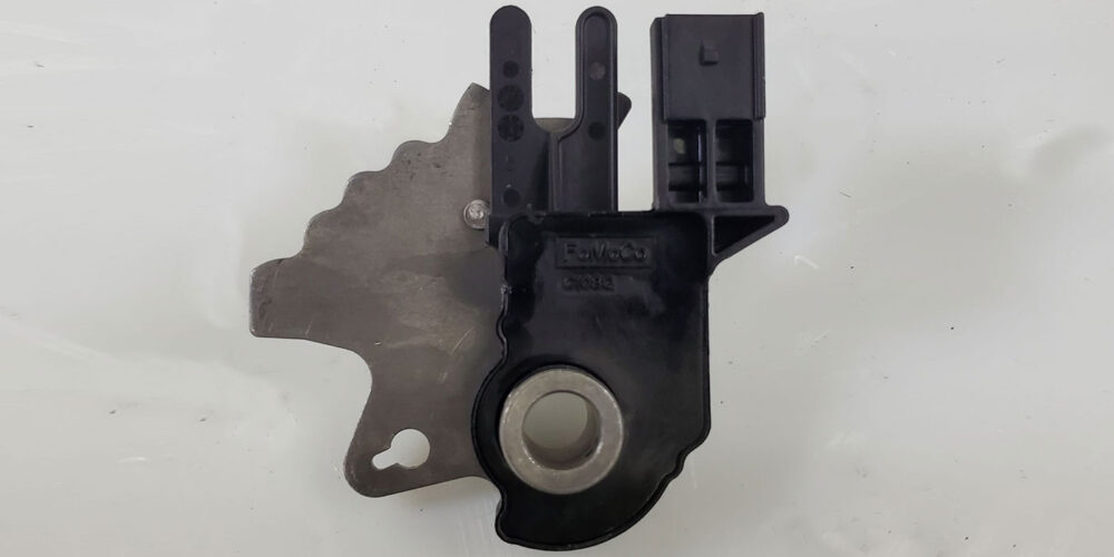
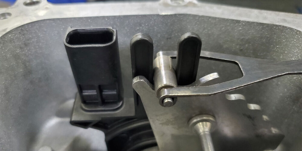
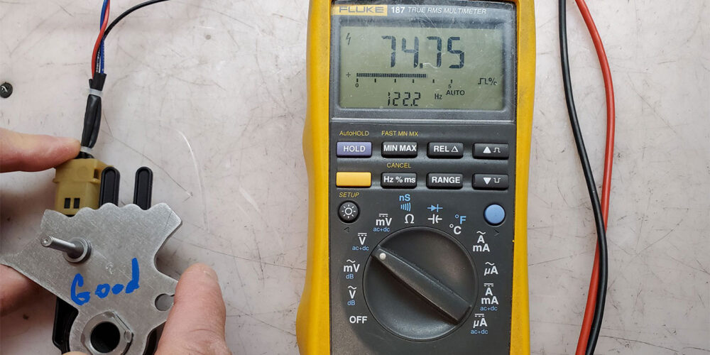
The Ford 6F35 transmission uses an internal Digital Transmission Range (TR) sensor (Figure 1, above) to provide a fixed frequency duty cycle to the Transmission Control Module (TCM) for five different manual control lever positions. They are Park, Reverse, Neutral, Drive and Low.
The TCM uses this input to influence line pressure control, shift scheduling and converter clutch operation. This signal is also sent to the Powertrain Control Module and the Body Control Module over the High Speed CAN network for PCM and BCM (Body Control Module) for engine start and reverse lamp operation.
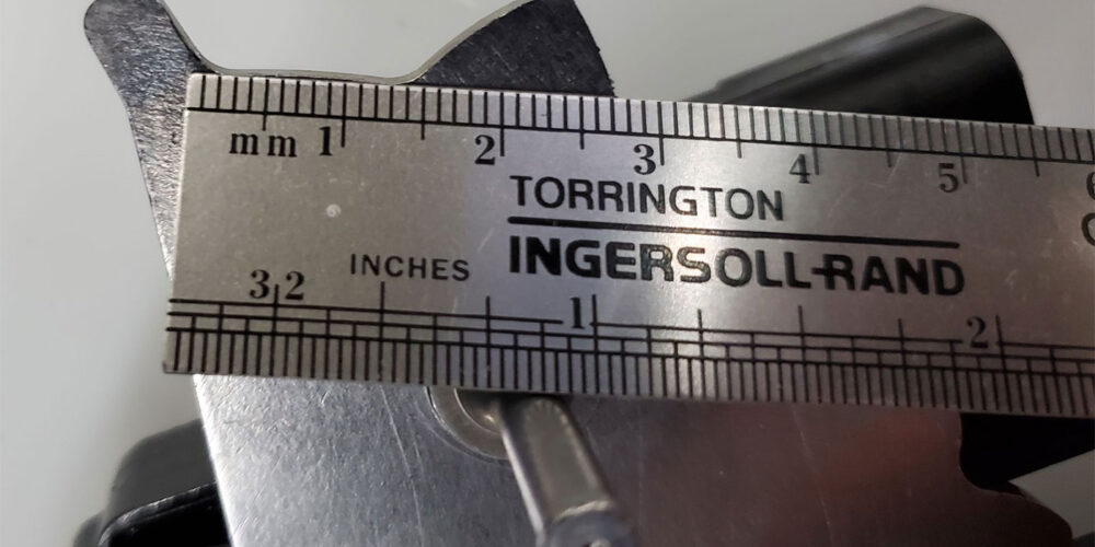
When this transmission is being replaced, sometimes it is noticed by the installer that there appears to be an excessive Park Wiggle Movement (PWM) of the selector lever. This is a normal characteristic of the sensor as the detent plate has a park valley that is approximately 15 millimeters in length (Figure 2).
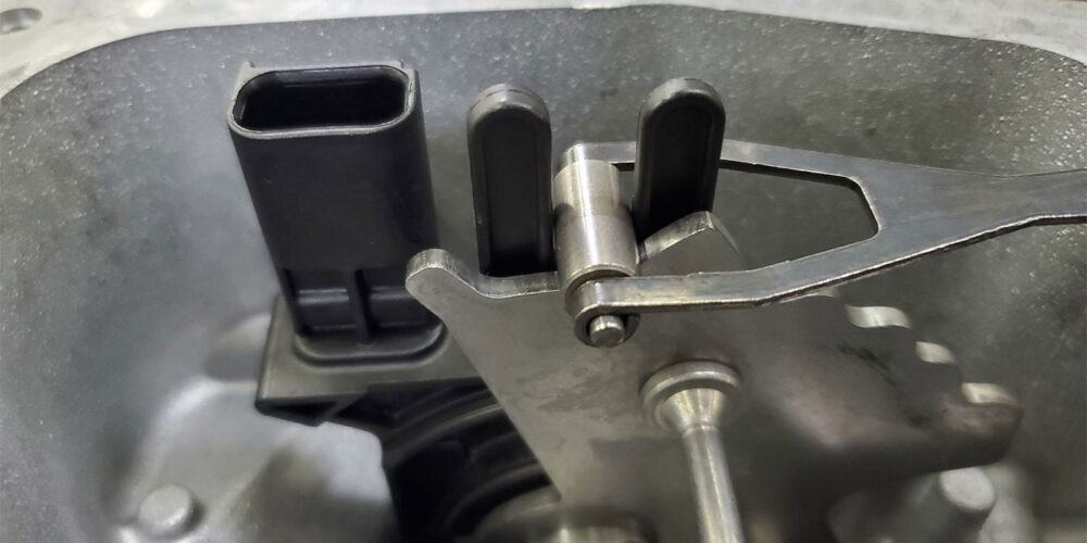
This allows for the Park Wiggle Movement as illustrated in Figures 3 and 4.
As such, the cable is not adjusted in the Park position, it is adjusted in the Drive position. With the adjustable cable end disconnected from the manual arm shaft lever, the shifter inside the vehicle is moved to the Drive position. The manual arm shaft lever at the transmission is then fully rotated in a clockwise direction placing the manual valve in the Low position. The lever is then moved one notch counterclockwise to place the manual valve into the Drive position. Now the cable can be adjusted, attached, and locked into place. The vehicle is then checked for proper Park hold, reverse light, and start operation in Park and Neutral.
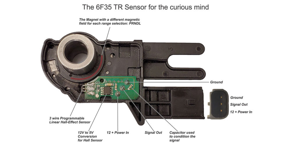
This TR sensor as mentioned earlier provides a fixed frequency duty cycle to the Transmission Control Module. In other words, it provides a Pulse Width Modulation (PWM) signal to the TCM. Ford uses this style of sensor in the 5R110W, the 6R140, and the 10R80 transmission. This style of sensor requires only three wires: power, ground, and a signal wire. This makes for less wiring in the harness loom. But have you ever wondered how a sensor can provide a PWM signal to the TCM? Usually, the TCM/PCM provides a PWM signal to a pressure control solenoid of some sort. In my curiosity to understand this, I consulted with an electrical engineer so I can learn. And now I would like to share it with you.
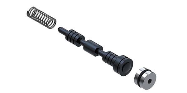
I took apart the TR sensor to show the internal electrical components to help explain the simplicity of this little device. As you look at Figure 5, the three terminals are identified. The 12-volt supply is converted to 5 volts for a Programmable Linear Hall-Effect Sensor. This little Hall Sensor also has three terminals. A 5-volt supply, a ground, and the signal out which is a duty cycle of a pulse width modulated signal. This little programmable Hall sensor generates this signal by reading a varied magnetic field from the magnet on the rotating shaft of the sensor.
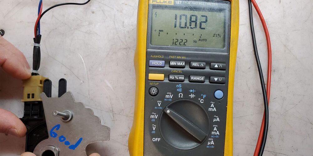
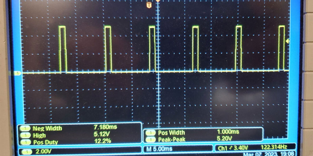
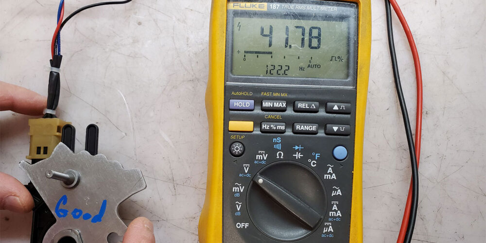
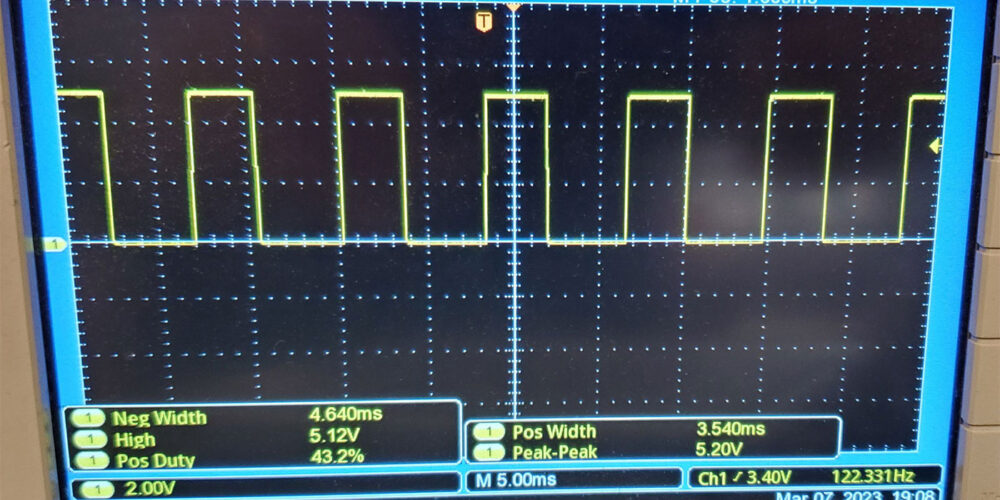
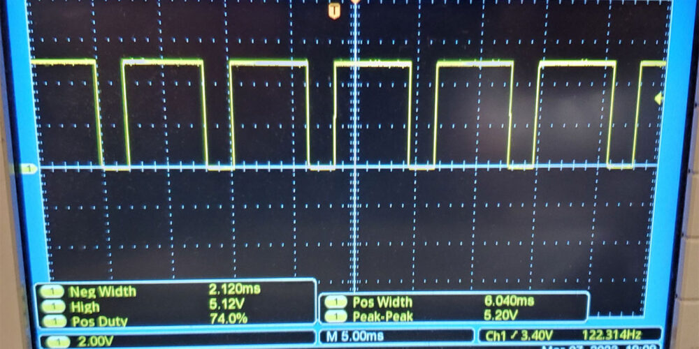
We simulated this on a work bench to show how this signal is displayed in both a DVOM and a scope. In Park, it will produce an 8 to 25.8 duty cycle (Figures 6 and 7).
In reverse it will be 37.50 to 49.31 (Figures 8 and 9).
Neutral is 54.54 to 62.49 (Figures 10 and 11).
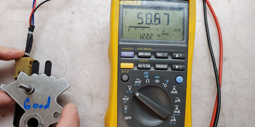
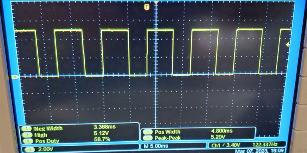
Drive is 67.35 to 81.15 (Figures 12 and 13).
Low will reach 81.15 to 92 (Figures 14 and 15).
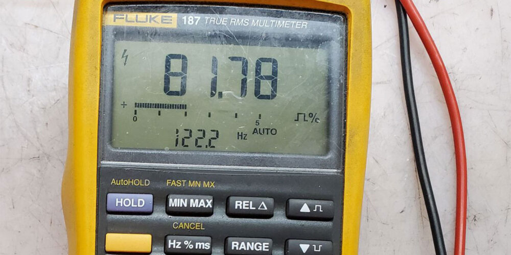
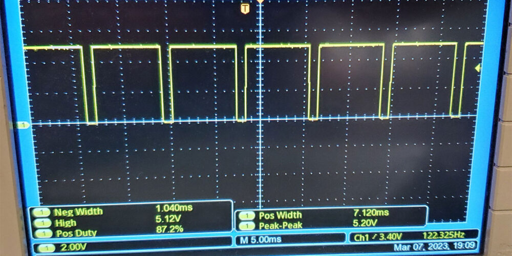
Figure 14 Figure 15
This single wire duty cycle signal from the transmission to the computer is referred to as “Sensor A circuit” in some of the DTC descriptions it can set should it malfunction. These codes are:
- P0706 TR Sensor A Circuit range/performance malfunction due to a mechanical or electrical fault where the sensor did not change or is intermittent.
- P0707 TR Sensor A circuit Low due to a short or open (power/signal)
- P0708 TR Sensor A circuit High due to an open circuit (ground)
- P1702 TR Sensor A circuit Intermittent due to open or shorts (connectors-wiring)
- P1705 TR Sensor Not Indicating Park/Neutral During Self-Test due to sensor misaligned or in the wrong position during the self-test event.
- P1921 TR Signal duty cycle is detected to be out of range (sensor failure)
Without a doubt, this TR sensor in the 6F35 transmission is authentically a PWM sensor from having Park Wiggle Movement to producing a duty cycle of Pulse Width Modulation signal. A Pretty Wacky Multifunctional sensor indeed.