Shift Pointers
- Author: Jon Glatstein, ATSG Electronics Consultant
New voltmeter lead set helps troubleshoot bad connections
Once in a great while something comes along that makes you slap yourself on the forehead (ala Homer Simpson) and wonder why you didn’t think of that. The Teslite (teslite.com) test lead is one of those items – a very simple tool that can find a bad connection or contact with a quick push of a button.
We have all fought the ubiquitous but elusive bad ground, dirty contact or loose connection. You know the one – all your voltage readings are correct until there is actually a load on the circuit. Then all readings go someplace in a hand basket and you cannot figure out why. Everything says it should be working. Well, what if you could put a load on the circuit you are testing with the push of a button? By comparing the loaded and unloaded voltage readings you can zero in on the problem in no time. This is what the Teslite does.
On the handle of the positive lead there is a red button (see Figure 1). Pressing this button places a load across the voltmeter leads. Modern-day digital multimeters have a typical input impedance of 10 megohms (10 million ohms). That puts virtually no load on a circuit when you are testing it. The Teslite throws a very low resistance across the test leads, effectively decreasing the input impedance of the meter and greatly increasing the current flow in the circuit.

With this increased current flow a small resistance, such as a bad connection, will cause a significantly greater drop in voltage. This greater voltage drop will be apparent in your meter readings, basically forcing the bad connection out of hiding. In case you are a glutton for punishment, the math is in Figure 2.

So, how can we use this magical function in the real world? Well, let’s start with checking for a bad ground. Attach the black lead of the Teslite to the positive battery terminal (preferably, right on the post). First, just go right over to the negative terminal with the big yellow probe. Your meter will read battery voltage with a minus sign in front of it. Now push the red button on the big yellow probe and watch the meter while you do it. If there is a significant change in voltage at this point, the battery is bad.
Now move the big yellow probe over to a clean spot on the transmission, and again push the button. Again, the voltage should not change much. Most OEMs allow a 0.3-volt drop in a ground circuit, so you want the voltage reading to change less than 0.3 volt. If the change is more than that, you have a bad ground.
Move the Teslite probe to the engine side of the ground cable and test again. Keep getting closer to the battery until the change no longer occurs. When you get to that point you have just passed the place where the bad connection is.
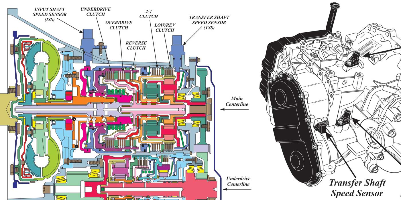
How about the voltage getting to the solenoids in a 604? In a 2004 Dodge Neon, this power goes through quite a bit before it gets to the transmission. It comes from the battery, through a fusible link to fuse 14, then to fuse 17 and out to the transmission control relay (also known as the EATX relay), and finally to pin 4 of the case connector (see Figure 3). Here it provides battery voltage to power the solenoids and to pull up the pressure-switch signals.

With the Teslite you can test all this at once. Connect the black lead to the battery negative post. Unplug the transmission and connect the big yellow probe to pin 4 of the wiring-harness side of the case connector. Have an assistant turn the ignition on, and you will see battery voltage on the meter for a couple of seconds until the computer realizes that the connector is unplugged. Remember the exact voltage reading you got.
Now hold the red button down and have your assistant turn the ignition off and then back on. Again remember the reading. The two readings should be within a few tenths of a volt of each other. If they are, this circuit is fine and you should look elsewhere for your problem.
If the reading changes a lot, move the big yellow probe up to the relay power input from fuse 17 at pin 47 of the relay. This should be hot at all times, so there is no need to cycle the ignition. Simply attach the probe and compare readings with the red button pressed and not pressed. If the readings are the same, the problem is either the relay itself or the wiring from the relay to the transmission. If the readings are different, the problem is in the power-distribution system.
Anyplace where a load on a circuit should not make a difference can be tested quickly and easily with the Teslite. If there is any resistance in a circuit, the Teslite will show it.