Torque Converter Tech Tips
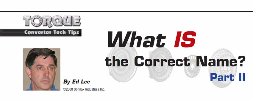
- Author: Ed Lee
In 1955 the automotive industry finally standardized the shift quadrant on all vehicles. From that time forward, all shifters would read from left to right (or front to back) and the order would be: Park, Reverse and Neutral, followed by the Drive ranges.
This concept of a uniform approach seems fairly simple, but keep in mind that the industry was already more than 50 years old when this happened. As automotive designers invented new concepts or refined previous approaches to mechanical design, standardized naming does not appear to have been very high on their list of priorities. They sometimes named the part as they envisioned its function, or they may have reused a name previously associated with a similar design.
Mechanics and rebuilders have added to the confusion, identifying and naming parts on their own instead of researching to learn the correct names. It is not difficult to understand why the standardization of names within the automotive industry has taken so long. The torque-converter segment of the automobile industry is no exception. As a result, it has suffered from misunderstanding and miscommunication since its infancy.
Last month we traced the origin of the names for the four main components of the torque converter: impeller, stator, turbine and cover. Unfortunately, the problem does not end with these four components. Torque-converter rebuilders use many different names when referring to the individual parts that make up these main components.
Many of the names used for the parts of the torque converter can be traced back to its beginning, and some even go back well before the converter was invented. The term “blade” is a good example. The “blade” was a part of early turbines, used to harness the power of falling water. In a torque converter, blade most often refers to the part that separates the individual cavities that direct the flow of oil through the impeller or turbine. The stator is also divided into individual passageways and what separates the cavities in the stator may also be referred to as blades, although they are an integral part of a one-piece casting. The part of the stator that contains the individual passageways is simply called the “stator housing.”

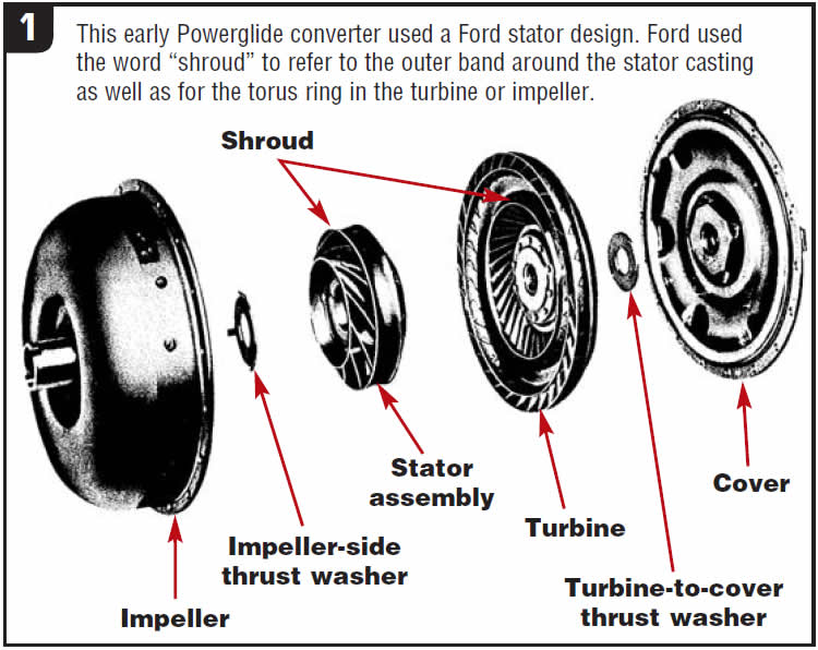
On some Ford stator assemblies, there is a band around the outside diameter of the part. Ford calls this band a shroud. The term “shroud” is somewhat confusing, because Ford also uses “shroud” to refer to the concave ring in the impeller and turbine that the oil passes around as it travels through the parts. The Powerglide converter shown in Figure 1 used a Ford stator design, with a steel “shroud” wrapped around a cast housing. Most other original-equipment manufacturers (OEMs) refer to the concave ring in the impeller and turbine as a “torus ring.” Calling the band on the Ford stator a “shroud” and the concave ring in the impeller and turbine a “torus ring” is the best way to avoid the confusion.
The individual parts of a one-way clutch also are contained within the stator housing. They consist of an inner race, outer race, and either a sprag or roller-clutch assembly in most production units. A mechanical diode, or possibly a clutch eliminator, is often used in high-performance units.
At one or sometimes both ends of the stator are the stator caps. These removable caps make the internal parts of the stator accessible and help to absorb the thrust forces from either the impeller or the turbine. Stator caps may be made of aluminum or phenolic material; they also may support a thrust washer. If the cap supports a bearing rather than a washer, it is referred to as a bearing adapter. Most stator caps and thrust washers or bearing adapters and corresponding bearings are not interchangeable from side to side. It is better to identify them by location such as “impeller-side stator cap and/or thrust washer” or “turbine-side bearing adapter and bearing.”
The drive or driven portion of many mechanical components are called “hubs.” The term is used in many areas inside an automatic transmission. The inner splines of most friction clutches are fitted to clutch “hubs.” The term is also correctly used for the drive or driven portions of some torque-converter assemblies. The turbine hub is the driven member of the turbine assembly, and the impeller hub is the pump-driving member of the impeller assembly.
Unfortunately, many individual parts of the main components that make up a torque converter are referred to incorrectly on a daily basis. The term “snout,” for example, has been used for both the pilot and the impeller hub of the converter. When questioned about the specifics of the term “snout,” some rebuilders will call the pilot the front snout and the impeller hub the rear snout. Others will call the impeller hub the front snout and the pilot the rear snout. It seems that rebuilders cannot even agree which is the front and back of a converter.
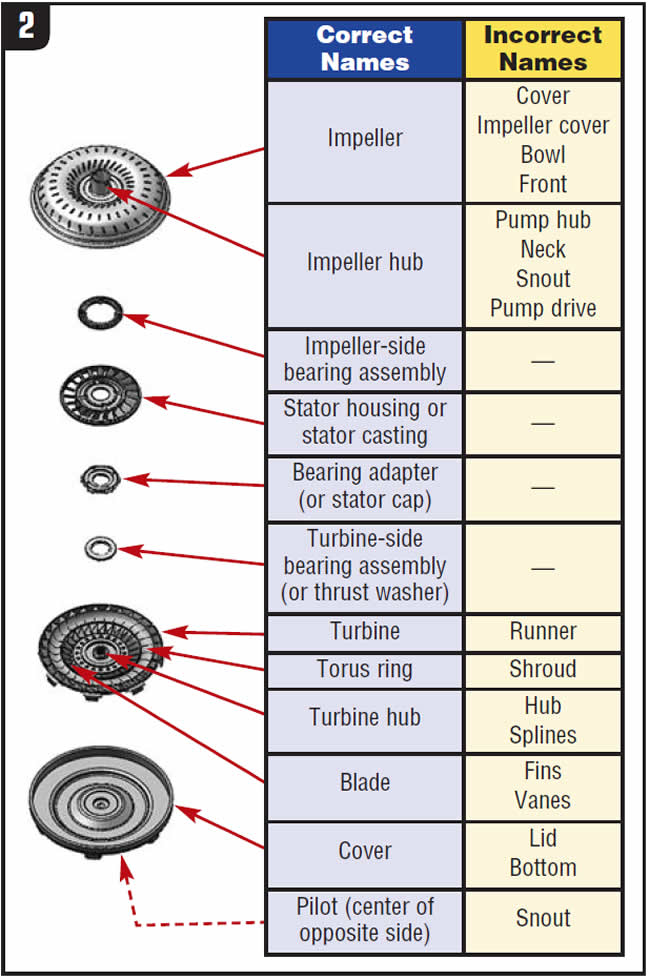
As a group, we need to work at standardizing our use of torque-converter component names. Ordering parts, sharing information on repair techniques, diagnosing and understanding problems, and executing effective rebuilds can be made easier only if we speak the same language. Figure 2 contains another list of correct and not-so-correct terms often used in our industry. Think about your own habits and decide whether we need to standardize our terms.
Ed Lee is a Sonnax Technical Specialist who writes on issues of interest to torque-converter rebuilders. Sonnax supports the Torque Converter Rebuilders Association. Learn more about the group at www.tcraonline.com.


