Tech-to-Tech
- Subject: Diagnosis of malfunction in drive-by-wire system
- Vehicle Application: 1957 Chevy
- Essential Reading: Rebuilder, Diagnostician, R & R
- Author: Jeff Bach
Diagnosing a troubled ECM reveals a compromised “drive by wire”
A while back I was paid a visit by two fellows who were trying to pick my brain or possibly get me to come across town to help them figure out a problem they’ve been having. It concerned a technical malfunction in one of their powertrain systems.
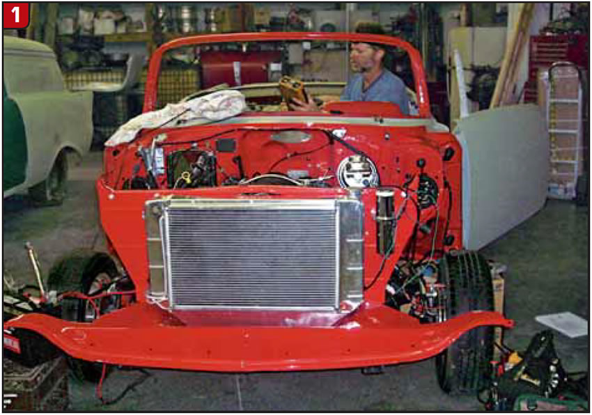
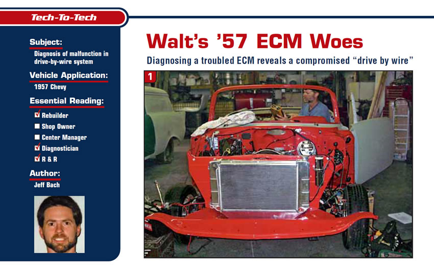
They started off by dropping names of some good friends of mine who put them on my trail. Then they let me know I was their last hope and cost wasn’t an issue. With the introductions and amenities out of the way, I gave their story a listen. It seems that Walt, who is semi-retired and loves to keep busy, bought himself a nice ’57 Chevy convertible. He stripped out the original Chevy powertrain and replaced it with a late-model (’05 GTO) LS2 6.0-liter/six-speed automatic “drive-by-wire” (Figure 1) powertrain. Dave, on the other hand, is a retired General Motors Corp. worker. He liked the idea of 400 hp and decent gas mileage – plus the fact that the dressed engine is easy to look at (Figure 1) and the undressed version (Figure 2) is fairly unusual in these parts. Both fellows purchased their wiring harnesses and preprogrammed LS2 ECMs from a company that specializes in street-rod changeovers.
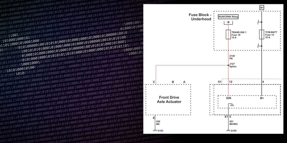
“Drive by wire,” if you’re not familiar, is a system of throttle control using a set of accelerator-pedal-position (APP) sensors to tell the engine-control module (ECM) what the driver would like to have happen with the throttle. The ECM uses a throttle-actuator control (TAC) module, which opens and closes the throttle plate to the desired angle. The TAC module contains a set of throttle-position sensors that operate linearly opposite each other the same way as the APP sensors. Contained inside the TAC module is also an actuator that is driven by the ECM that moves the throttle plate itself.
Dave’s powertrain operates fine with his ECM, but Walt’s engine would not run smoothly and they couldn’t get communication to a scan tool. Now these are not your average try-a-few-things-and-throw-in-the-towel sort of fellows. They have been through the street-rod performance people’s technical support and tried all of their suggestions. They then sent the whole wiring harness and ECM back to the company and had them retest their work. They got word that the ECM was no good and sent the company a new ECM, which Dave got through GM with his discount. Upon reinstalling the harness with all the proper power and ground hookups, they now have a different problem! Walt’s car idles smooth but won’t accelerate. The scan tool now communicates with the ECM and receives codes. Dave had pretty much concluded that the ECM was again at fault but couldn’t get the technical-support guy to agree with him. It seems that they wanted him to do a relearn of the system to clear.
This is where I came in.
My initial contact with these two fellows was in more of a consultation and advisory capacity than as an on-site diagnostician. I explained to them that I wouldn’t be able to help much if I couldn’t get scan data. I wanted them to have at least done power and ground checks and have a good ECM. This entailed a lot of testing and parts switching on Dave’s part, with plenty of good data to share. Dave has built his own car from the ground up and likes to do everything himself whenever possible. Walt is more of the investor sort than a hands-on guy and has commissioned Dave to help him keep his street-rod project on a forward-moving path. I had also informed Dave that I would like to have access to the harness and components that I was going to be testing – mainly the ECM and TAC systems – which he assured me were accessible (Figure 3).
When I ran out of things to tell them to try and hoops for them to jump through, I finally packed up my scope and my road bag and headed over to the body shop where the car was being assembled. The body-shop guy doesn’t want to put the car any further together until they get the powertrain issue resolved, since part of his job will be to bury all the wiring beneath polished aluminum and chrome covers.
I hooked up the scan tool with a CANdi module and did a code check. I found a U0101 TCM data code; a P2138 and a P060D, which are both TAC-related codes; and a P0315 crankshaft-position (CKP) system-variation learn code. The P060D code did not show up in the code chart for the specified powertrain, and I have never encountered this code before. I assumed it could have been related to a programming issue. These ECMs have to be programmed so that they don’t need pass-key data and aren’t looking for the usual inputs from places such as ABS, TCS and IPC modules.
When you take on one of these projects you are accepting that certain standards are no longer in place. The ground beneath you can feel a little shaky at times. I attempted to move on to the other TAC code and proceeded to diagnose it using the factory trouble tree, which turned out to be a short-lived effort in futility.
I was able to verify that the wiring from both the APP sensors and the TAC module was intact. The P0315 code is normal for a new ECM and requires you to hold down the throttle until the engine hits the rev limiter for the ECM to “learn” the variations in the crankshaft and the crankshaft sensor. Of course, since this is not possible with the TAC situation, that code will have to be dealt with later.
I decided to turn to my trusty scope to see whether I could get some usable data from a known good source and gain some insight into the workings of the TAC system. I connected one channel to each of the TPS sensors on the TAC and got the image in Figure 4 using Dave’s control module.
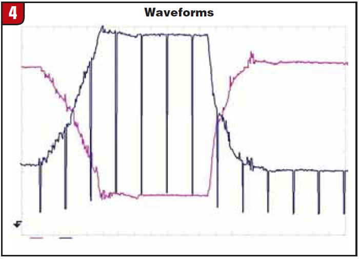
This image came from the TPS sensors at the TAC module. It looked a little scary to me at first, but after doing a little studying I realized that it’s quite normal. This was obtained by going wide-open throttle and release. The spikes you see on sensor 2 coming down are actually pulses put there by the ECM every 157 milliseconds (mS) to determine the integrity of the circuits. It looks to see whether they show up on the other sensor. If they do, it assumes the two circuits are shorted together. You can see this a little better in Figure 5.
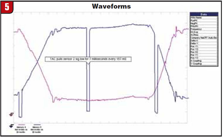
You will also see this signal when scoping the APP sensors. The ECM looks to see whether the APP sensor 2 is more than 2.05 volts for more than 300 mS (skips one pulse) to set a code.
Next, I switched to Walt’s ECM and took the same readings, which are displayed in Figure 6.
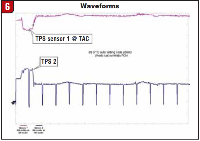
This image shows that the TAC TPS signals start to move normally toward each other then change and go back to below reference as the ECM drops control of the TAC motor. It is at this point that the codes set and the throttle valve is left at idle no matter where you put the pedal. Clearing the code and starting again is the only way to get the throttle to start to move again. In Figure 7, I looked at the APP sensor and the TAC TPS signal to see whether they coincided.
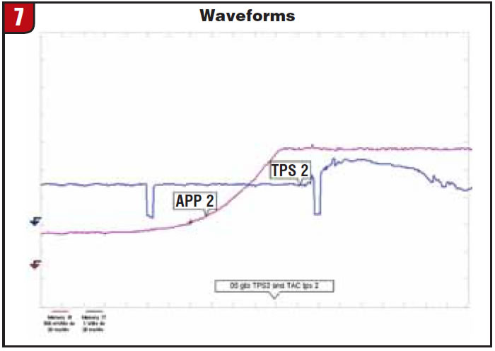
There seems to be somewhat of a delay between the time the APP sensor sees throttle-pedal movement (about 180 mS) and the TAC TPS starts to react. That’s about the speed of an eye blink. To determine the reason for the delay, I connected the scope to the TAC TPS signal on one channel and used the other to monitor the driver circuit for the TAC actuator. The waveform shown in Figure 8 shows a blowup of the period just when the ECM shuts down the system and goes to “idle only” mode.
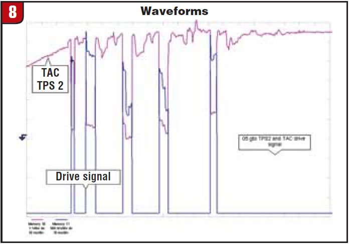
This was for me the “clinching waveform,” showing that the noise in the TPS signal coincides with the ECM’s attempt to drive the actuator and indicates an internal ground issue. I am now in full agreement with Dave that the problem (however unlikely the street-rod people think) has to be in the ECM. The new one is on order.

Jeff Bach is the owner of CRT Auto Electronics, an ASA-member shop in Batavia, Ohio. For more information on this topic, contact Bach at 515-732-3965. His e-mail address is [email protected].
This copyrighted article is reprinted with the permission of AutoInc., the official publication of the Automotive Service Association (ASA). To learn more about ASA and its commitment to independent automotive service and repair professionals, visit www.ASAshop.org or call (800) 272-7467.