
Technical Training
- Author: Bernie Thompson, Automotive Test Solutions
- Subject Matter: Electronics
- Issue: Understanding voltage
The modern vehicle contains over a mile of wire, up to a 100 modules and thousands of electrical connectors. Looking at a wiring diagram of one of these vehicles can be a bit over whelming. Without a doubt the complexity of these vehicles has reached an all-time high. With onboard radar and laser detection systems it may seem like you are working on the parts of some short of aircraft or spaceship, and not that of a road vehicle. So how does one navigate these complicated systems? When diagnosing this amount of wire, modules and connections, one can no longer guess at where the problem may lay.
Whether you are working on a spaceship or a modern vehicle, it will be necessary to understand basic electrical principals. Perhaps one of the most important principals in diagnosing electrical systems is the voltage drop. This is where voltage is consumed by resistance.
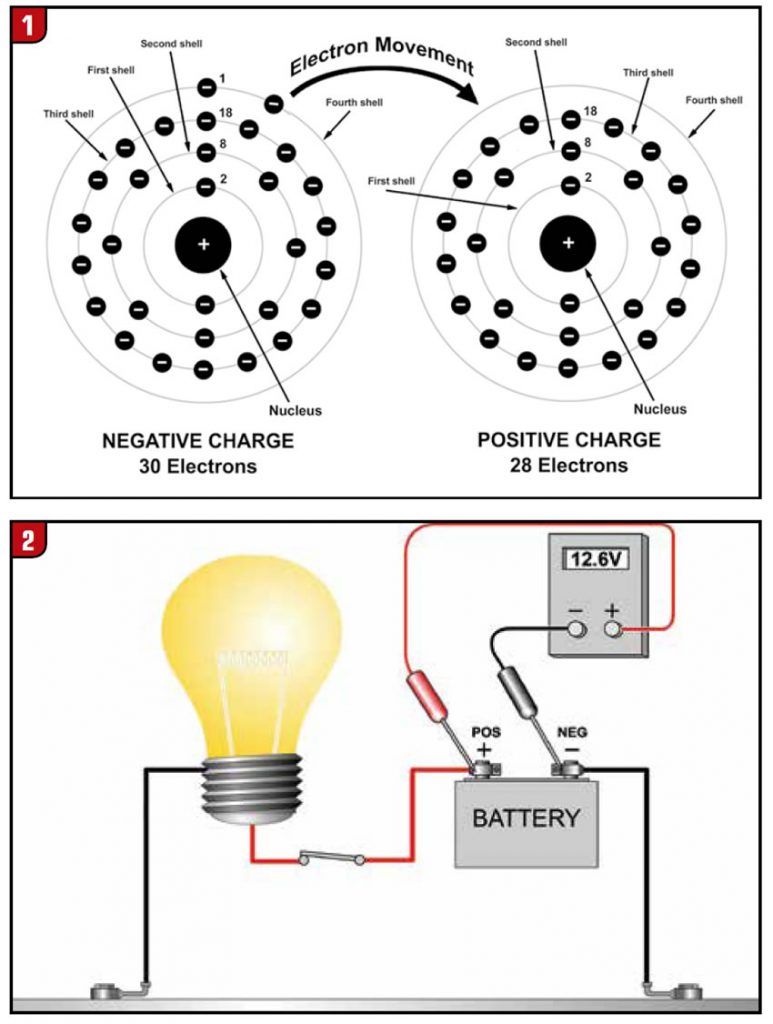
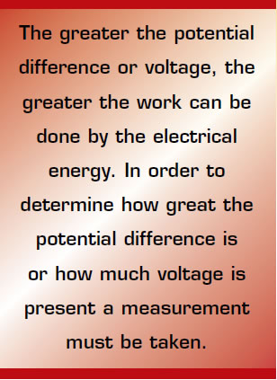
Voltage is electric energy or electric pressure. This electric energy is the potential difference between two points with a charge present between them. This charge arises when an atom becomes imbalanced by losing an electron as seen in Figure 1. In most atoms, there are an equal number of protons (positive charge) as electrons (negative charge) and the opposite charges of these two kinds of particles balance out or are in equilibrium. It is possible to break electrons free from their orbits about the nucleus, causing an imbalance in charge. In order for the atom to lose an electron the atom must have an outside force acting on it. This force must exert more energy on the electron than the bond between the nucleus of the atom and the electron. This force will be a large energy source that can be caused by light, magnetism, heat or chemical energy. As this energy is applied to a number of atoms, more atoms become imbalanced causing a greater difference of charge. When this occurs a potential energy is created. This energy is referred to as electrostatic potential, which is the difference of charge in an electric field. This charge is typically measured in units called voltage. The greater the potential difference or voltage, the greater the work can be done by the electrical energy. In order to determine how great the potential difference is or how much voltage is present a measurement must be taken.
In order to make a voltage measurement a reference must be provided. The voltage measurement is based on two probes: positive and negative. The potential difference between these probes is all that is measured. This potential difference is converted into units of voltage. In order for the total voltage in a system to be measured a fixed reference point such as the earth (ground) must be used so the total potential can be calculated. When measuring the voltage in a vehicle the lowest point of potential will be the negative post of the battery. Therefore the ground probe will be connected to the battery negative post (ground), while the positive probe will be connected to the circuit to be tested. The difference between the probes, or voltage units measured, will then be displayed on the measuring device as shown in Figure 2. The entire test is based on where the two probes are placed. This is very important because the only result displayed on the measuring instrument is the difference between the two test points.
When testing a circuit several methods of measurement can be used: Ohms, amperage and voltage. Ohm is the measurement of the resistance that is within a circuit. The problem with using this type of measurement is that the circuit under test will need to be open. This means the ohms can only be measured in a circuit that is not under load; therefore the resistance in ohms can measure low (good) but can be too high under a loaded condition.
One such example is if an 18-gauge wire were used as the battery cable on an automotive starter. This wire would ohm with very little resistance but under the load of the starter motor draw would create a large amount of resistance to the current flow. This is caused by a limited area of the conductor that can flow electrons. With a low electron flow rate such as with an Ohmmeter, this limited area would not be seen. However, this limited conductor area when exposed to high current flow will allow resistance to occur to electron flow. In the case of the starter motor the resistance would be so high to a high electron flow rate that the electric energy (voltage) consumed by the wire would release enough heat to melt the wire, thus breaking the wire and the electrical circuit. This could also be illustrated with a highway in a large city. If one were to watch the flow of vehicles at two o’clock at night there would be very little resistance to the vehicles moving on the highway. This is due to very few vehicles occupying the highway. But if one were to watch the same highway at the same location at seven o’clock Monday morning you would find a totally different outcome. The vehicles would be backed up on the highway due to high resistance. Neither the highway area, nor the number of lanes change between these two times. The change that occurred was the number of vehicles that are occupying the highway. Now think of the highway as the electrical conductor and the vehicles as the electrons. In order to see resistance the load must be high. So the use of an Ohmmeter to measure vehicle electrical circuits is not a good choice for most vehicle diagnostics.
Amperage measures the electrons flowing through the circuit. This electron flow is referred to as current. Current is always the same throughout the circuit so no matter where the current is measured within the circuit the results will always be the same. The current is a good indicator of the circuit’s condition such as; low current indicates high resistance, high current indicates low resistance, and the correct current indicates the circuit is functioning as designed. Therefore amperage can show a problem is present within a circuit, but cannot be used to locate where the problem is within that circuit.
Voltage measures potential difference of the circuit. This potential difference (voltage) can be used in a loaded circuit to locate where the problem is within that circuit. The electric energy (voltage) that pushes the electrons through the circuit will be consumed by any resistance within the circuit. By measuring where the voltage changes within the circuit one can locate the resistance of that circuit. This measurement is referred to as voltage drop. In order to test a circuit for voltage drop the circuit will need to be loaded. Current must be flowing through the circuit so the electrical energy can be consumed or used by the resistance or load (the load would be the unit within the circuit that is there to use the electrical energy such as; a head light, a blower motor, a solenoid, etc.). Voltage drop is a reduction in voltage in an electrical circuit between the source and the load.
Unwanted resistance, which creates voltage drop can occur either in the positive or negative leg of the circuit. Voltage drop is caused by resistance in the circuit that uses some of the electrical energy that would normally go to the load.
This reduction in energy is also a reduction in the work that can be done by the load, thus causing problems in the electrical circuit. This electrical energy that is used to cross the resistance in the circuit uses some of the potential difference, or voltage. This voltage change, or voltage drop, in the circuit will show the location of the resistance within the circuit.
Now let’s look at voltage with a slightly different twist to it as shown in Figure 3. Think of voltage as the electrical pressure that pushes the electron through resistance. Now picture yourself being the rider on the bicycle (voltage) and the electron being the bicycle. The bicycle or electron will not move without an outside force acting on it; it will remain at rest. In order for the bicycle to move, you (voltage) will have to provide energy or force to the bicycle. While this force can be applied to the bicycle, it does not have to move the bicycle. Think of this as a bicycle that is against a starting gate as shown in Figure 4. The rider can put pressure against the pedals but the bicycle does not move. In order for the bicycle (electron) to move several things must occur; the gate must fall, the circuit must be complete, and the bicycle must return to the place it started from. Once the gate falls the pressure will move the bicycle around the circuit. The rider, just like voltage, is the pressure to move the bicycle or electron; the more pressure applied the more work can be done.
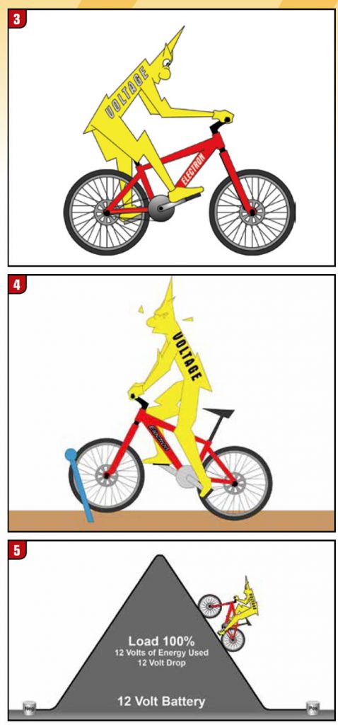
If you were climbing a hill on the bicycle as shown in Figure 5 you would need to apply pressure on the pedals in order to get up the hill. The more pressure you applied on the pedals the more work you could do. The bicycle will not climb the hill by itself, it will need an outside force acting on it; it will need you (voltage) to apply this force. The force or effort that you apply from the bottom of the hill to the top of the hill is the potential difference.
This potential difference is the amount of energy that was used or consumed in order to climb the hill. This potential difference is the lost energy that occurred to push through the resistance of the hill. This is similar to what happens to the voltage in a circuit, the voltage has to push the electrons through the resistance or load and in doing so loses energy.
Once you have expended the energy to climb to the top of the hill you will not have to expend very much energy to coast down the hill. There will be a slight loss of energy due to the friction between the road and tire, the bearings, and the air resistance. This energy loss is similar to the resistance of the conductor in a circuit. There will always be a small amount of voltage remaining in the negative side of the circuit to push the electrons through the resistance of the conductor. This is usually hundredths or tenths of a volt. Any resistance in the circuit will have voltage present in order to force the electron through the resistance. A small resistance will have a small voltage drop. Where a large resistance will have a large voltage drop. At the point there is no resistance within a circuit there is no voltage present in the circuit. Voltage in a circuit is only present to push electrons through the resistance. If there is voltage present there is resistance present. This is much like riding the bicycle if there is a hill still remaining you will have to have energy left in order to climb the hill. However current is always equal throughout a circuit. Electricity is current or the movement of electrons, and voltage is what pushes these electrons through the circuit. Current within a circuit is always constant, and voltage within the circuit is changing based on the resistance within the circuit.
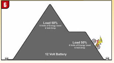
If there is more than one hill it will take energy to climb each hill as shown in Figure 6. After each resistance there will be lost energy that can be measured as voltage drop. The total of all the voltage drops within the circuit will equal the applied (source) voltage. The larger the hill, the larger the energy loss is; the smaller the hill, the smaller the energy loss is. If both hills are equal the energy will divide equally between them. In a good circuit there will be a very small voltage drop on each leg of the circuit, positive and negative. This is due to the resistance of the conductor, which usually produces voltage drop of hundreds or tenths of a volt. Additionally each switch, transistor, MOSFET, or relay will produce voltage drop of hundreds or tenths of a volt within the circuit as well. The load will use all the energy in order to do the work. So on the positive circuit leg you should have very close to source voltage, and on the negative leg you should have very close to 0 volts as shown in Figure 7.
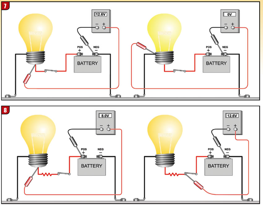
If there is a voltage change on the positive or negative leg of the circuit this is an indication there is unwanted resistance in the circuit. If you are testing the circuit at the load; on the positive leg the voltage drop is indicated by a reduction of voltage due to the resistance before the load consuming some of the energy and on the negative leg the voltage drop is indicated by an increase of voltage due to the resistance after the load needing energy to push the electrons through the resistance. By changing the test point on the circuit the location of the problem can be found as shown in figures 8 and 9. The voltage difference is only measured between the probes. So once the resistance is not located between the probes the voltage on the positive leg will show close to source voltage and on the negative circuit leg will show close to 0 volts. A circuit is comprised of both positive and negative circuits, each of which makes up 50% of the total circuit. When testing the circuit the first test points should be at the load this will determine which leg of the circuit has the problem, positive or negative. If there is not a voltage drop present, the circuit is good and no further testing will be needed for the power and ground circuit. If there is a voltage drop present the probes will then need to be moved in order to locate the problem as shown is figures 8 and 9. If you need to measure the positive leg drop you can move the lead to the positive post of the battery. Now the measurement will only show the voltage between the probes, which is the positive leg.
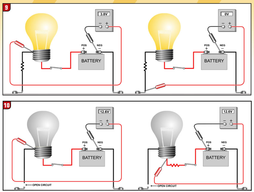
Always remember the circuit must have current flowing through it in order to test it. If the circuit is open there will always be source voltage present to the point of the open circuit as shown in Figure 10. Since no current can flow in an open circuit there cannot be a voltage drop present so instead of a voltage drop, source voltage will be present to the point where the open circuit occurs. Be aware that an open circuit can hide a resistance contained within the circuit as shown in Figure 10. If no current is flowing then no voltage drop can occur showing the resistance.
Where there are two resistances within a series circuit the voltage between these resistances can be used to convey data to a control unit. When these resistances are in this configuration they are referred to as a voltage divider. This is a very common circuit that is used in the vehicle electronic systems that is based on voltage drop. With a basic understanding of these principals and a little practice you will soon be able to navigate these complex systems. When diagnosing the modern vehicle just remember to follow the data. The data that you gather during your diagnoses will always guide you to the problem.