TASC Force Tips
- Author: Tory Royce
When it comes to reaming valve bodies, there are always questions about how to approach things the “right” way. It pays to keep in mind that reaming a valve-body bore to allow installation of an oversized valve or sleeve is a precision operation and must be viewed with the mindset of a machinist. Properly maintained equipment, correct setup and the right cutting fluids are critical in achieving success. Here are a few suggestions we have compiled over the years in response to common inquiries.
A primary factor in successful reaming is how effectively the reamer is piloted. Though often overlooked, it is critical that the reamer follow the centerline that was established by the original machining process. There are three ways to establish and maintain proper reamer alignment.
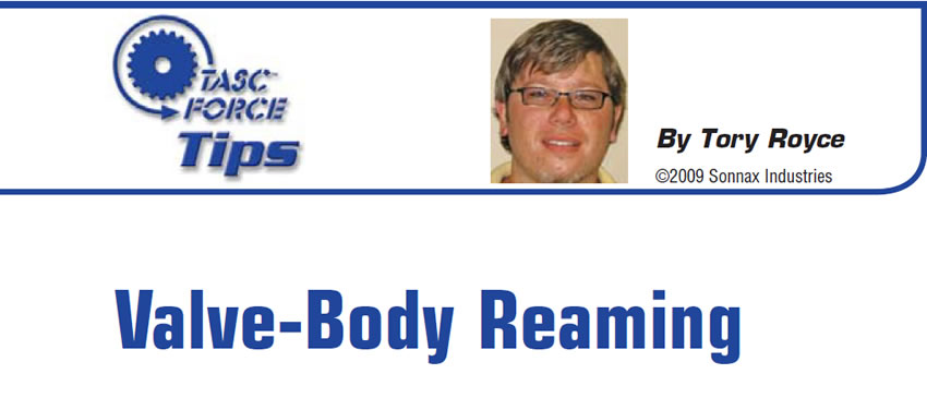
The first method is a self-piloting reamer (Figure 1). This type of reamer will have a properly sized “nose” to help guide and center the reamer in the bore. Though simple, they are nonetheless effective in certain applications. Unfortunately, there are limitations with this type of reamer depending on the bore design and depth. The most-obvious limitation: This reamer cannot ream to the bottom of the bore.
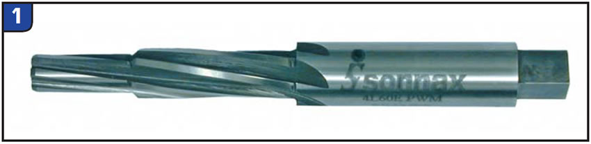
The second method accomplishes the centering function by using a reamer jig inserted in the bore to provide a path and support for the reamer (Figure 2). The jig ensures that the reamer will start its cutting operation straight and true. Again, limitations exist with this design. Excessive wear and factory machining processes can cause concentricity issues.
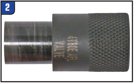
Finally, some situations require a fixture for proper alignment (Figure 3). The fixture allows the piloting operation to be performed externally by using a guide pin and an adjustable collar to establish centerline and a reamer guide to hold the reamer in alignment.
Once you have a valve-body and piloting method set up, it helps to take an inventory of the tools needed. Some tool kits require multiple reamers, so keep this in mind and pay close attention to the instructions for the proper sequence. The reamer(s) can be driven by hand with a speed handle or by using a high-torque, low-speed power drill. An electric drill can be used, but the speed is more easily maintained with an air drill and adjustable regulator.
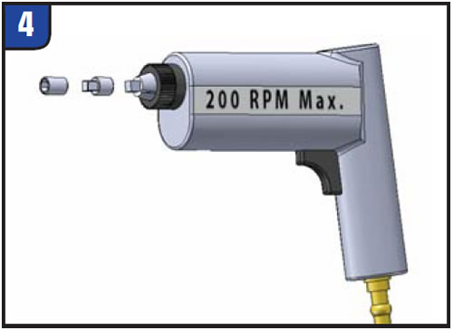
A wobble-drive adapter should be used between the drive tool and reamer socket to prevent side loading (Figure 4). It’s important to maintain a constant speed of no more than 200 rpm; otherwise, the surface finish and bore size can be negatively affected. Always clean the valve body thoroughly before beginning, to ensure the best finish possible.
A cutting fluid designed for aluminum is critical for the best results. Products such as ATF or rust penetrants should never be used for this purpose. Reamer damage, a poor surface finish and/or an incorrect bore size can result. Water-soluble cutting fluids such as MobilMet S122 or Lubegard Biotap work best, but old favorites such as Tap Magic also work well.
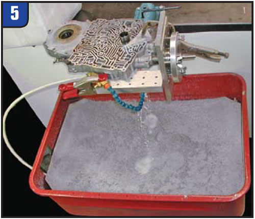
For volume cutting operations and for best results with power reaming, a reaming station with constant lube has proved to be the most-efficient setup (Figure 5).
When reaming by hand, soak the reamer and bore thoroughly before starting. Occasional reapplications thereafter are recommended to keep the tool and bore lubricated. Always turn the reamer clockwise, never backward. Try to maintain a fluid, continuous motion, with little to no forward force. The reamer should pull itself through the bore, so avoid pushing it harder. This will only hurt the finish and possibly cause it to “corkscrew,” which can result in an undersized bore.
It is advisable to clean chip buildup periodically during the process to keep the finish intact. Chip buildup also can cause the reamer to bottom prematurely, resulting in sleeve-fitment issues and sticking valves, so pay close attention to this. When using a fixture, never break down your setup until you are completely finished reaming. This can cause the reamer to cut off center and induce sticking and hydraulic leaks because of the loss of your original centerline.
Now that we have the basics out of the way, what happens when you have fitment issues when you’re finished? If the sleeve and/or valve(s) are too tight after reaming, here are a few suggestions:
Chuck the reamer in a power drill and run it in and out of the bore at 500 rpm. This will burnish the bore and remove any surface imperfections. Alternatively, use a piece of coat-hanger wire bent over a small piece of Scotch-Brite pad chucked in a drill to remove flashing material. Be very cautious not to remove too much material and cause a leak.
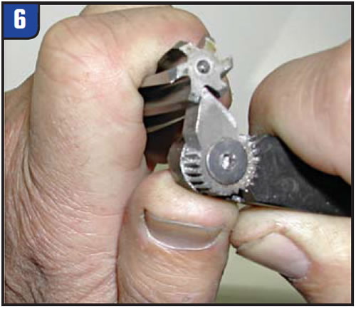
Check the reamer for aluminum buildup. It’s not always visible at first, but under a magnifying glass this will be evident. It may be necessary to clean the edge of the reamer flutes periodically with a product such as an EZE-LAP paddle or a sharp cutting-tool bit (Figure 6). Drag the tool along the inside edge of the flute, toward the tip, to remove the buildup.
If a sleeve is too loose, here are a few tips to avoid or help correct a problem:
As mentioned earlier, always use a wobble-drive adapter between the reamer socket and drive tool. This prevents side-loading and oblong bores. If you are using a speed handle, keep hand motions as fluid and circular as possible. Avoid exaggerated movements that can force the reamer to wobble in the bore.
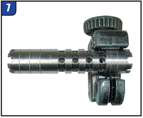
If a sleeve is too loose, you can use a tubing cutter to tighten things up (Figure 7). Lightly scratching the sleeve in a couple of locations can help with this. This technique also can help with a leaking end plug in some instances.
When setting up your valve body in a fixture, make sure the guide-pin action is as smooth as possible when the pin is stroked in and out of the bore. You should not feel any steps when inserting the pin. Continued adjustment should be done until the action is completely smooth.
I hope this will help clarify the most-common inquiries about reaming. It helps to remember that all these suggestions were obtained through trial and error, so don’t be afraid to contact Sonnax Tech Support if you have any questions or concerns. With a little care and process-development time, anyone can make a worn-out valve body perform as good as new.

Tory Royce is a Sonnax Technical Support Specialist and a member of the Sonnax TASC Force (Technical Automotive Specialties Committee), a group of recognized industry technical specialists, transmission rebuilders and Sonnax Industries Inc. technicians. E-mail Sonnax Tech Support at [email protected] or call 800-843-2600.


