Technically Speaking
- Subject: Design, operation and diagnosis
- Unit: Aisin Seiki AS68RC
- Vehicle Applications: Isuzu, UD and Mitsubishi midsize trucks; Dodge 26,000-lb. commercial vehicles
- Essential Reading: Rebuilder, Diagnostician
- Author: Wayne Colonna, ATSG, Transmission Digest Technical Editor
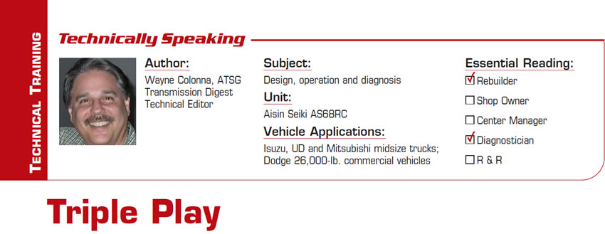
The AS68RC is a rear-wheel-drive Aisin Seiki six-speed transmission that began its life in the U.S. with Isuzu, UD and Mitsubishi midsize trucks (Figure 1). Since the 2007 model year, it has been used in Dodge incomplete-chassis and commercial vehicles with a GCVW rating of 26,000 pounds and the 6.7-liter Cummins diesel engine.
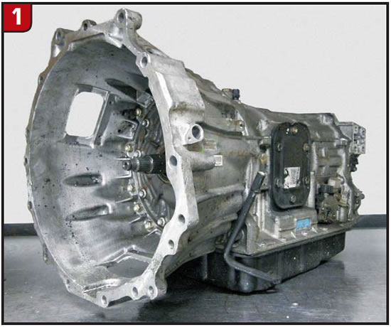
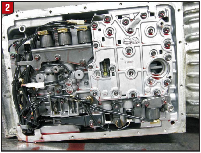
The transmission contains three drive-clutch assemblies (K1, K2 & K3), two hold-clutch assemblies (B1 & B2) and one sprag (F1) to produce six speeds through a triple planetary gear train (P1, P2 and P3). The complex aspect of this unit has to do with the electro/hydraulic controls the computer uses to control these five clutch assemblies in addition to the converter clutch. Attached to the valve body are eight pressure switches, four on/off solenoids and four linear solenoids, most of which you can see in figures 2 and 3.
ATSG has produced the industry’s only AS68RC technician’s guide that contains complete hydraulics along with valve-body, pump and case mapping that reveals how the computer controls this unit. It is an outstanding detailed manual that makes sense out of what is a very complex operating system. If you were to look at data-stream information with a scan tool, you would certainly understand what I am talking about.
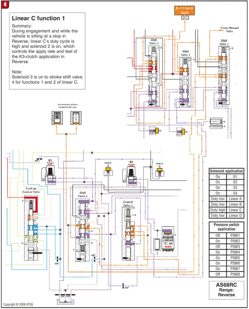
With eight pressure switches going on and off and eight solenoids being operated, it is quite an experience, one that leaves you scratching your head trying to make sense of it all. But once you understand what is occurring by viewing these schematics, you not only can make sense of scan-tool data but also will be able to diagnose and isolate malfunctioning solenoids and/or switches. Take, for example, linear solenoid C (Figure 3), which is used to control garage-shift engagements into both Reverse and Drive and to control converter-clutch application, making this a triple-play solenoid. And for any triple play to occur, other players need to do their part.
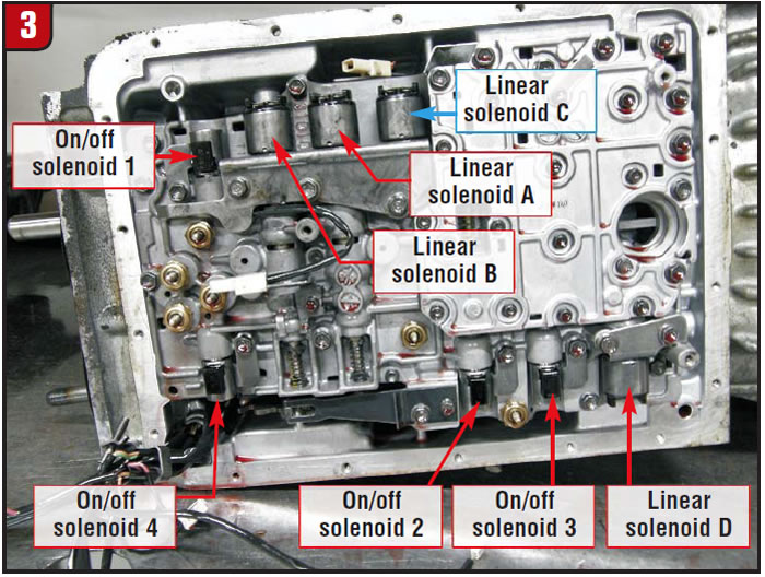
Figure 4 illustrates phase one in the two-phase process of engagement into reverse. The first phase occurs during the initial selection of reverse at idle with the brake applied. Shift solenoids 2 and 3 become energized (on) and the duty cycle for linear solenoid C goes high. This causes various valves to stroke, allowing regulated line pressure (identified by color orange) to be routed to a double accumulator set and the K3 clutch. This allows for a controlled, soft apply of the K3 clutch for a smooth reverse engagement.
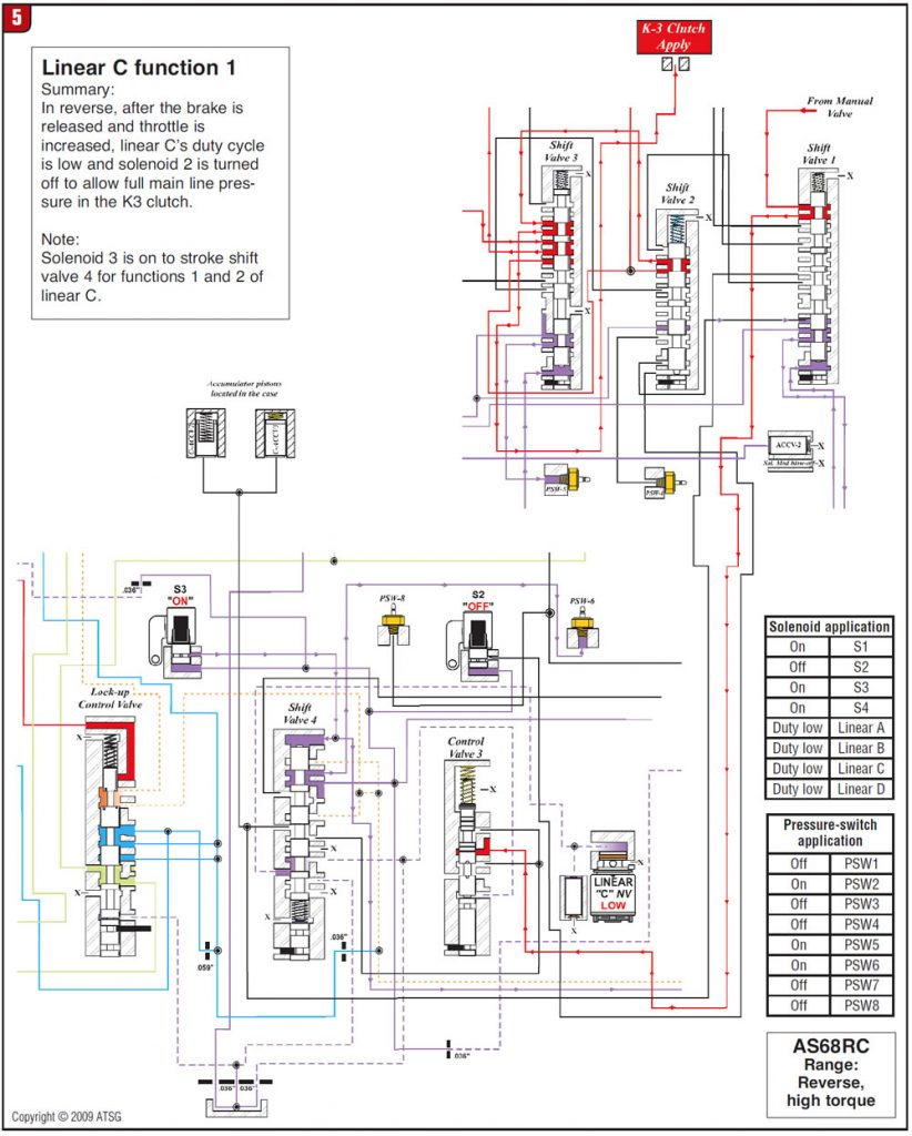
Once the computer recognizes that the brake is released and the throttle begins to be depressed, stage 2 is initiated (Figure 5). At that time shift solenoid 2 goes off and linear solenoid C’s duty cycle goes low. When this occurs, certain valves stroke in such a way that the double accumulator circuit is shut down and full line pressure clamps the K3 clutch down (identified by color red).
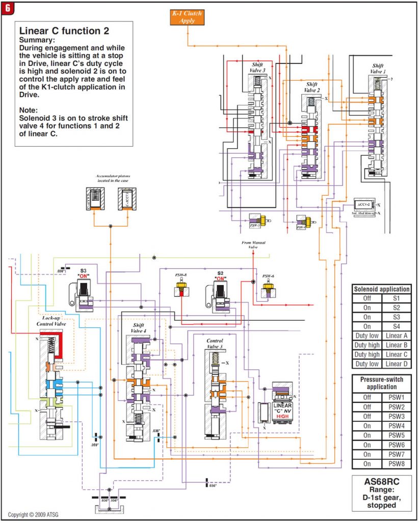
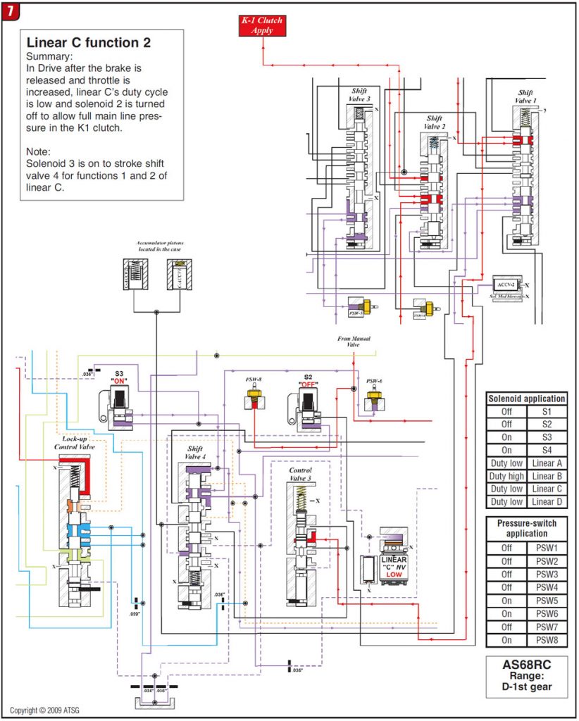
Figures 6 and 7 show the similar two-phase strategy for the drive engagement.
Figures 8 and 9 reveal how linear solenoid C controls converter-clutch apply pressure. You will notice that shift solenoid 3 needs to turn off for linear solenoid C to change its function.

In one sense this is similar to the operation of the 41TE transmission, in which the low/reverse solenoid becomes a TCC apply solenoid by the stroking of the solenoid switch valve in the valve body. But with the AS68RC, linear solenoid C is a triple-play solenoid with the help of shift solenoids 2 and 3 to give it its various functions. By just knowing this alone, you can already see the type of complaints that would occur should linear solenoid C malfunction. Since you now know the three different complaints one solenoid can cause, you can hit a home run on your diagnosis.


