
TASC Force Tips
- Author: Wayne Russell
Auxiliary coolers have been available for almost as long as automatic transmissions have. For many of us who have been around a while, most auxiliary coolers were used to supplement the factory transmission cooler for towing or other heavy-duty purposes. In the TASC Force Tips article “Contamination and Coolers” in the August issue, we discussed the need to replace some coolers, but I realized that there are no guidelines for choosing the right-size cooler to install.
The GVW rating on most coolers is the total rating when it’s used in addition to the OE cooler, not as a replacement for the OE cooler. Perhaps you have installed a cooler to replace an in-tank transmission cooler. How do we know which one we need? What is big enough? What about in cold regions: Will the oil flow? What effect does wind have? These are just a few of the questions.
Most original-equipment OTW (oil-to-water) coolers are in the radiator and transfer heat from the transmission fluid to the cooling-system coolant. OTW coolers are very efficient and compact. The vehicle manufacturer has determined the amount of heat generated (for intended use) and made the cooler size adequate to transfer this heat into the radiator and coolant. The next step is to transfer this heat to the air by moving the air (by vehicle travel or fan) through the radiator. Considerations such as A/C, operating temperatures etc. are all part of the design process. We simply do not have the resources to redesign a cooling system for every vehicle we work on. Neither do the cooler manufacturers.
How do we make a choice? The simplest step is to re-install an OE cooler. This may mean a new radiator. Most radiators are cheaper now than ever before. If the vehicle manufacturer provided an additional oil-to-air (OTA) cooler and you are dealing with a badly contaminated system, you should replace this cooler also.
Now let’s look at various cooler options available:
- Fin and tube (turbulator inside varies and can affect cooler performance)
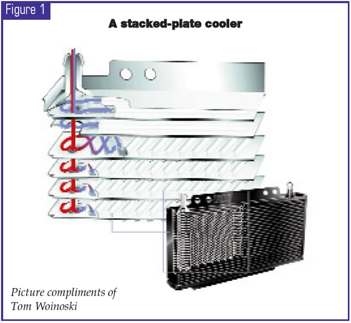
- Stacked-plate design (looks like a radiator)
- Oil pan with ribs and/or tubes
- Heat exchangers (common in marine and heavy trucks)
- Coolers with passive bypass
- Coolers with thermal bypass.
Coolers are sized by length, width and thickness. More important is how much heat the cooler can “reject” or transfer to the surrounding air or liquid. The temperature of the fluid is important, and most transmission experts like to keep it under 200° F – hard to do when engine coolant is at 210° F or more!
Heat flows from hot to cold. Outside air temperature is very important to OTA coolers! The hotter the air is, the slower the rate of cooler “rejection” (the process of transferring heat to air). Certainly at 50 mph, a steady supply of air at 100° F will provide adequate cooler performance. But when the torque converter is working hard (such as when the vehicle is climbing up a steep incline with a big load) is when it generates the greatest amount of heat. The vehicle speed may be slower and thus reduce the amount of air to which the cooler can reject heat. In order to handle these situations we need to look more closely at cooler efficiency.
Certainly size matters, but there are critical design features of coolers that we need to look at. First we will look at fin-and-tube coolers. The simplest form is a tube with fins attached to the outer surface. With nothing inside, hot fluid passes through, and heat is transferred to the tube and flows to the fins and onto the cooler ambient air. Simple, but not the most-efficient cooler. Only the outer layer of fluid can transfer heat, and most of the fluid passes through with little cooling.
Years ago, manufacturers added turbulators to the inside of the cooler tubes. This improved the heat transfer in two ways: There was greater area to contact the hot fluid, and there was more contact with the tube. The design of the turbulator varied, and so did cooler performance. Simple and inexpensive designs were a flat, twisted piece of aluminum; more-elaborate and effective extruded-aluminum designs did a superior job. Unfortunately, they look alike from the outside, so many shops bought the lower-cost and less-efficient coolers.
In supplemental cooling, these can be adequate. However, we must use better designs for stand-alone OTA coolers.
Marine-type OTW? Heat exchangers (also used in medium and heavy trucks) are very efficient. This is close to radiator design. We don’t see much of this because of cost and complex plumbing.
Stacked-plate cooler designs are better suited for stand-alone applications, and flow is a big reason. With many paths for the oil to flow from one side to the other, flow across the plates is slower, allowing more time to reject (transfer) heat to ambient air. Internal cooler design plays a big role in efficiency. A good example to look at is OTA coolers made for Ford Super Duty trucks in comparison with Long True Cool coolers (the black ones).
Long manufactures both coolers, and the Ford version can reject (transfer) more heat per square inch than the True Cool counterpart (same thickness). These are important design points when you’re dealing with heavy-duty applications. Unfortunately, this information is not readily available. Late-model Ford products (police Crown Vic, for example) also use this design cooler.
What we have done is to use existing applications (OEM) and try to model these in the application we are working on. For example, if a Ford F-350 diesel has an OTA cooler 22 inches x 6 inches and 3⁄4 inch thick, we could use this cooler on a similar vehicle and expect to get similar results.
According to Long
Manufacturing, the OE-series coolers are about one-third more efficient than the same size True Cool series. So you must increase size if you try to match. Also, doubling thickness does not necessarily double the cooling! Ambient-air temperature, fluid temperature and flow, air flow, cooler pressure and location of the cooler all play a role in how the cooler will perform.
Cooler flow is very important, and we are seeing most vehicle manufacturers increasing oil-line sizes from 5⁄16 inch to 3⁄8 inch. Although a small increase, this can improve flow by more than 30%. This can make a big difference in keeping a transmission cool and lubricating vital transmission components. Another flow problem is in cold weather. Not all of us live in the tropics, and winter conditions can be quite brutal. ATF gels around –32° F. Even at 0-10° F, if we start a vehicle and drive off, the transmission lube system will be dry. This does happen, and solutions exist.
Cooler bypass systems help solve this problem. Passive bypasses are simply passages in the cooler that omit inner fins or turbulators and allow flow of cold fluid. Other designs are mechanical and use a temperature-sensitive valve to regulate fluid flow back to the transmission until the cooler warms enough to allow flow, or simple mechanical designs using a valve or checkball and spring (such as Ford E4OD and 4R100).
Long Manufacturing released a MAX COOL series recently. These kits include an optional bypass system that is plumbed into the cooler supply and return lines and uses a special thermal wax that expands and contracts with the temperature. This moves a valve, and fluid flow to the cooler is regulated by temperature. Colder fluid is redirected to the transmission return line until fluid warms and gradually flows through the cooler. This system always assures adequate lubrication. Be sure to install this on all vehicles that will operate in cold temperatures (especially below 0° F). This is the same design used inside the 4R55E valve body, and it works very well.
Naturally, we want prime real estate! But remember that a cooler installed in front of the A/C or radiator will affect these systems. As air flows through the transmission cooler and picks up heat, it will reduce the effective cooling at the A/C condenser or radiator. It is a good idea to look the cooling system over on any vehicle in the shop. Check for leaves and debris between the A/C condenser and radiator, a fan clutch that will not pull air, an electric fan that does not run, or low coolant level or too much antifreeze in the coolant. Remember, water transfers heat better than antifreeze, and if you have too much antifreeze, the cooling system will not cool effectively.
Wind chill is not a factor for coolers. Although a constant supply of cold air may make it difficult to get “up to temperature” in some cases, it will not cause fluid or air temperatures to go below ambient. Wind chill applies only to warm-blooded creatures.
I did mention oil-pan cooler designs. Although they have existed for years, they contribute little to cooling a transmission. Often they increase volume but add little to heat rejection, so I can’t consider these an option for stand-alone cooling.

Wayne Russell, president of Russell Auto Inc., Manchester, N.H., is an associate member of the TASC Force (Technical Automotive Specialties Committee), a group of recognized industry technical specialists, transmission rebuilders and Sonnax Industries Inc. technicians.


