Up to Standards
- Subject: Design, operation and diagnosis
- Unit: NVG 245 transfer case
- Vehicle Application: Jeep Grand Cherokee
- Essential Reading: Rebuilder, Diagnostician, R & R
- Author: Mike Weinberg, Rockland Standard Gear, Contributing Editor
Jeep is the originator of four-wheel-drive vehicles, and even though the brand has been owned by numerous corporations over the years, it is still the centerpiece of four-wheel activity. The top-of-the-line Jeep model is the Grand Cherokee – or WK series, in Jeep speak.
Once upon a time Jeep was the dominant player in the market, but Escalades, Expeditions, Range Rovers and other brands are crowding this lucrative market. To avoid being left behind, Jeep redesigned the Grand Cherokee in 2005 with new interiors, suspensions and power-plant combinations, and improved drivelines. Part of that redesign was the introduction of the 245 transfer case produced by New Venture Gear, a division of Magna International.
The Grand Cherokee as of 2007 has as power-plant options the 4.7-liter Hemi V-8, a 3.7-liter V-6 and a 215-horsepower Mercedes diesel capable of 376 lb.-ft. of torque. The 3.7-liter V-6 uses a Mercedes five-speed automatic transmission (W5A580), and the 4.8-liter Hemi is backed by a Chrysler 545RFE five-speed automatic transmission. Jeep also has added a 5.7-liter Hemi engine to this lineup.
The new suspension designs include independent front suspension and a new five-link rear suspension. These vehicle can be equipped with Dynamic Handling System (DHS), which hydraulically controls body roll, and an electronic stability program (ESP), which helps the driver maintain directional stability of the vehicle during hard cornering or drifting (intentional or otherwise) on any surface. Sensors throughout the car feed input to the computer, which adjusts braking and throttle opening to keep the vehicle on its intended path before the driver can react. Inputs from sensors that measure yaw, steering angle, brake-pedal force and position, wheel speed and throttle opening are all compared with a computer model to keep the driver alive and well and on the road by applying brakes, deactivating cylinders and activating the transfer case, all without driver input.

Vehicles equipped with the NVG 245 transfer case have two final-drive systems: Quadra Trac II and Quadra Drive II. Quadra Trac II uses the full-time operation of the 245 to send torque to the axle that needs it while simultaneously activating the Brake Traction Control System (BTCS), which will selectively apply brake force to stop wheel slippage. This system also uses Throttle Anticipate, which measures a quick throttle movement to prevent wheel spin under hard acceleration.
Quadra Drive II is a step up, with electronic limited-slip differentials for electronic control of the final-drive differentials. This is done through outboard clutch packs on the front and rear axles that electronically provide differentiation between the wheels during turns and tire slippage. This system is similar to the Honda Pilot system I wrote about a few months ago. This system uses the clutch packs between the differentials and the axles, the transfer case and the computer to allow axle slip or lock the axle, depending on need. This system will release the front-axle clutches to allow complete differentiation between the wheels in turns, like a rear-wheel-drive car, to prevent tire scrub and crow hop normally present in 4WD vehicles.
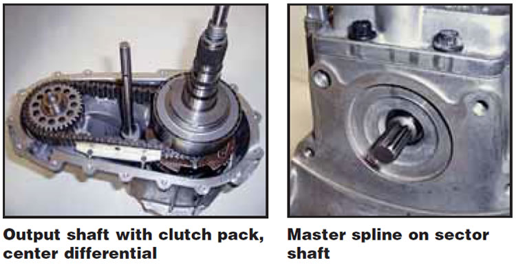
The NVG 245 transfer case is a full-time, active four-wheel-drive system. The transfer case splits torque 48% to the front axle and 52% to the rear axle through a planetary-type center differential coupled to an electronically activated clutch pack. An active transfer case is one that can anticipate wheel slippage and proactively send as much as 100% of the torque to the wheels that need it and, as wheel speeds equalize, return to the normal 48/52 split with no driver input. There is a 4W Low range that can lock the clutch pack, distributing torque 50/50 for off-road use, and a neutral range to allow the vehicle to be flat-towed behind another vehicle. A straight-cut planetary gear provides low reduction, and the low ratio is 2.72-1. Using low range on anything but dirt, sand, grass or other loose material will cause the transfer case to crow hop because of driveline windup.
The Grand Cherokee uses a final-drive control module (FDCM) to control the transfer-case active torque-biasing clutch and center differential and to communicate with other systems via the CAN C bus. The computer reads wheel speeds from sensors on all four wheels and interprets differences in wheel speeds as a slip. The computer program includes a complete model of the vehicle dynamics, which the computer compares with sensor inputs for vehicle speed, throttle position, steering angle, yaw rates, transmission gear position and brake-pedal position to engage the transfer-case clutch pack at the appropriate duty cycle to send torque to the appropriate wheels.
Correct tire size and pressure are absolutely critical for proper operation of these related systems. Mismatched tire sizes or pressures will cause the system to set codes, and shops that do not check the tires before performing any other diagnostic procedures will be wasting a lot of valuable time.
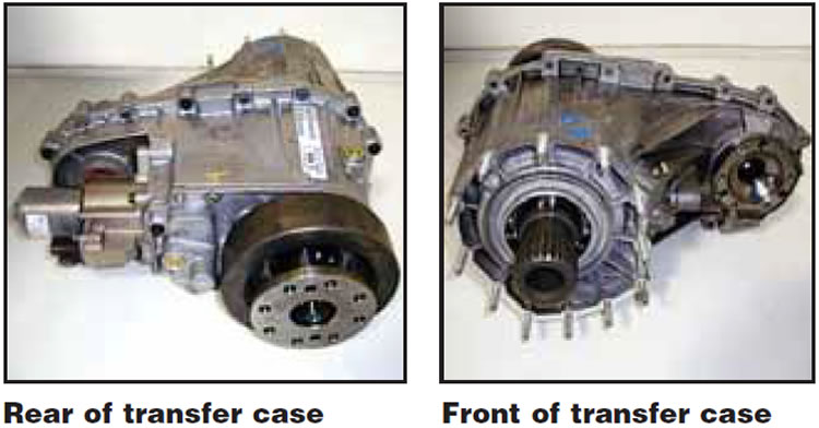
This unit is equipped with an electric shift motor and encoder. The motor is bolted to the side of the transfer case and drives the sector shaft to operate the clutch-pack apply, and to shift the transfer case to low range or neutral. The encoder tells the FDCM the position of the sector shaft during all phases of operation. The transfer case will always be in 4WD High unless the driver selects low range or neutral. The computer will not permit a shift to 4WD Low unless the vehicle is stopped or traveling under 3 kilometers per hour (1.86 mph) with the transmission in neutral.
To shift into Low range, there is a small chrome T-handle contact lever in the shifter assembly labeled 4WD Low. An indicator light in instrument cluster will signify low-range operation. Shifting into neutral for towing requires depressing a push-pin button near the range shift lever with a pen, and if the computer sees all the correct conditions, it will allow the shift. To avoid accidental shifts, the switch must be depressed for one-quarter of a second. The actual shift may take several seconds to occur.
If the vehicle is at rest and there is tooth-to-tooth contact in the transfer case, the shift will be blocked; letting the vehicle roll slowly will eliminate this issue. The computer will attempt five shifts and then light a signal on the instrument cluster, and the driver will have to return the shift handle to 4WD High and try again. Most owners of these vehicles will never use the shift lever and simply let the 4WD High Range full-time operation take care of all driving needs.
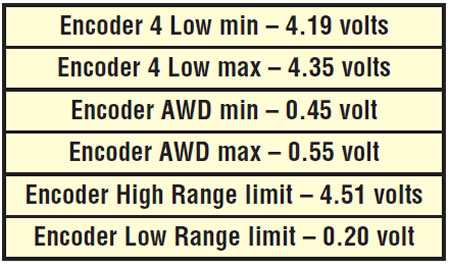
The transfer-case mode sensor (encoder) sends feedback to the FDCM regarding transfer-case position. The sensor is an analog linear position sensor that relays the motor-shaft position through a DC signal. The FDCM monitors the sensor position every two milliseconds when the ignition is in the on position and will continue monitoring it for 10 seconds after the ignition is turned off. The mode sensor draws current of 20 milliamps while operating.
The following chart reflects voltages that you should see to test the mode sensor/encoder. The FDMC uses a 5-volt signal to control the encoder, so do not test with 12 volts unless you wish to buy an encoder.
The shift motor/encoder has a master spline that must align with the sector shaft to attach the motor. New shift motors are shipped in the neutral position. You will have to shift the transfer case manually into the neutral position to attach the motor to the sector shaft. The shift motor is a permanent-magnet DC motor equipped with a position-holding brake, an internal gear train and an encoder or position sensor. Under stall conditions (maximum clutch application) the motor will draw a maximum of 32 amps at 72° F with 13.5 volts present at the motor leads. The unit also measures voltage polarity, which is used to control motor rotation directionally. These motors with the internal gear train are capable of exerting enough torque to lock the transfer-case clutch pack to full application, depending on the duty cycle commanded from the FDCM.
The NVG 245 transfer case’s clutch pack consists of single-sided paper-material clutch discs that are alternately splined internally and externally. The top plate has inside splines. The specified fluid for these units is Mopar NV245 Lubricant, P/N 05016796AA. The transfer-case capacity is 3.8 pints, and the factory recommendation for fluid replacement is 36,000 miles or 36 months. These units are hard on fluid, and I think the fluid should be replaced once a year or every 15,000 miles for good preventive maintenance. If you are rebuilding one of the units, make sure to presoak the clutches before installation until no more air bubbles exit the plates.
Like most late-model transfer cases, the actual design of the unit is simple, but as they say, “The devil is in the details.” The theory of operation is also simple, but diagnostics will require a good service manual with code listings and diagnostic trees, and the realization that multiple related systems must function together to operate correctly. The “good old days” where you could just remove and repair a unit are long gone. The guys who win are those who can see that a bad wheel-speed sensor, TRS or mismatched tires can be the heart of the problem. The worst place to be is on the end of the telephone with your first line being, “I took the unit apart but there is nothing wrong with it.”