Technically Speaking
- Subject: Operational characteristics
- Unit: U140/240
- Vehicle Applications: Toyota, Lexus
- Essential Reading: Rebuilder, Diagnostician
- Author: Wayne Colonna, ATSG, Transmission Digest Technical Editor
Oddities & Wear-Out, Part 1
Jim Dial and David Chalker have been working diligently in writing, illustrating and explaining the teardown, reassembly and operation of the Toyota U140/240-series transmission for an ATSG manual that is near completion. Available now is the U140/240 Technicians Diagnostic Guide, which is very helpful in understanding the hydraulic operation of the transmission and more. But in writing these two manuals, they have fielded many tech calls that enabled them to discover multiple complaints stemming from planetary failures, direct-clutch failures and solenoid faults, to name a few, aiding them in their work in putting together a manual for this transmission. From their work, this month’s article will cover a few oddities they discovered with some of the operational characteristics of this transmission, and Part 2 will cover some wear problems that they have been running into.
In past articles and bulletins we have talked about functions of the torque-converter-clutch (TCC) solenoid on the 4L30-E family and how on BMW and 2000-up Isuzu models this solenoid is responsible for TCC application and a reverse-inhibit solenoid. The U140/240 series has “one-upped” that, as we are going to find out in the following illustrations.
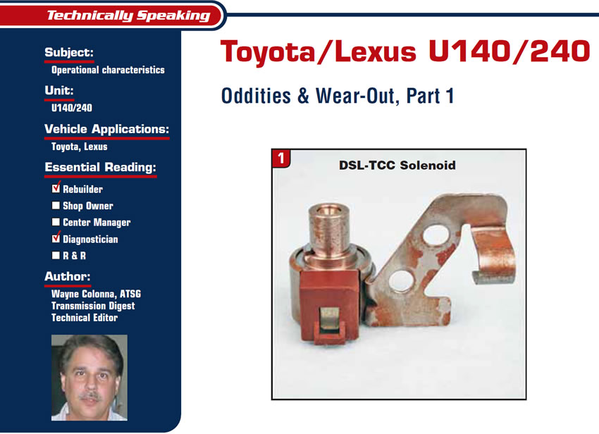
The DSL solenoid shown in figures 1 and 2 is normally closed and opens when it is supplied with battery voltage. This is a typical on-off solenoid, but its hydraulic function is the odd part.
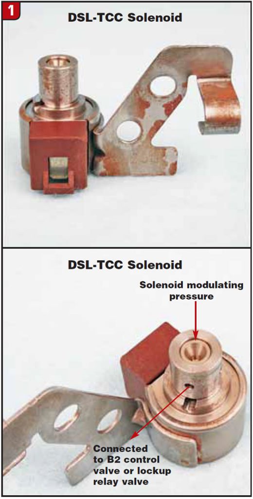
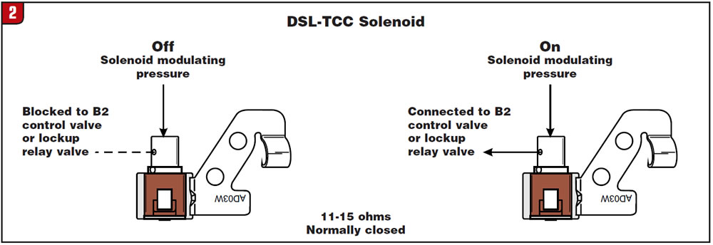
Figure 3 shows the DSL solenoid in TCC mode. When the TCC is commanded on, solenoid pressure strokes the lockup relay valve to the left and the TCC is applied.
Figure 4 shows the DSL-solenoid function in manual low. Believe it or not, this solenoid is actually energized in manual low to turn on the low/reverse B2 brake to provide engine braking.
The reason for this function is that the manual-valve circuits are the same in the D, 2 and 1 positions. The PCM controls upshifts based on the position of the transmission range sensor.
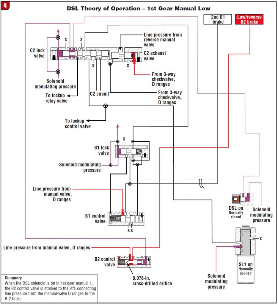
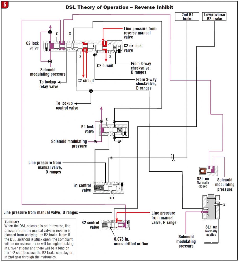
Figure 5 shows the DSL function during reverse inhibit. The DSL will be commanded on if the vehicle is moving forward, typically above 7 mph, and the driver selects reverse. Pressure from the DSL solenoid will travel through the C2 lock valve and stroke the B2 control valve to the left, shutting off line pressure to the low/reverse B2 brake.
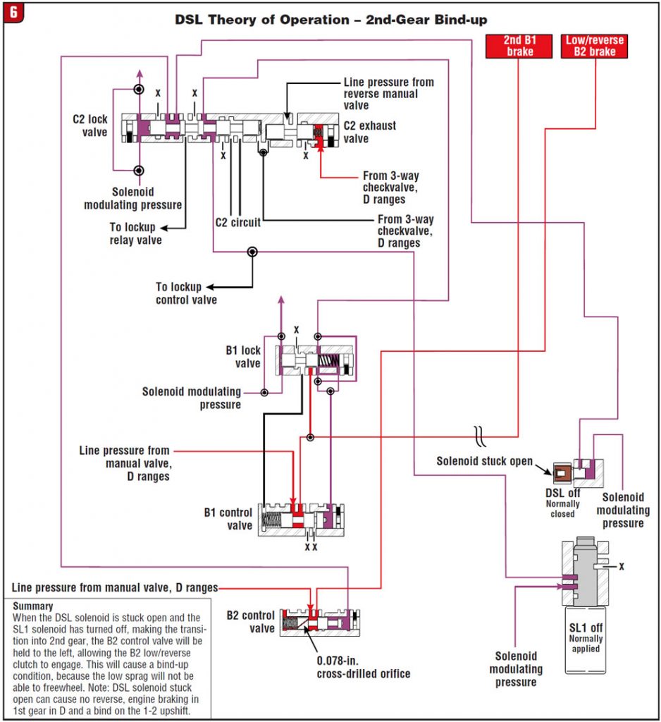
Here’s the oddest part of all: A call comes in through the tech line and the complaint is no reverse and a bind on the 1-2 upshift. As you can see in the previous figures, we can have a complaint of no reverse from the DSL solenoid if it is stuck open. Referring to Figure 6, notice that if the DSL solenoid is stuck open it also can cause a bind on the 1-2 upshift by allowing the low/reverse B2 brake to be on while the 2nd-gear B1 brake is on.
It would be very hard to find a common denominator for this complaint without the help of an oil-circuit diagram. The illustrations and information contained in this article are from the U140/240 Technicians Diagnostic Guide mentioned at the beginning. This manual provides theory of operation, passage identification and full oil-circuit diagrams. Aftermarket parts distributors and the ATSG bookstore have this manual available.
Part 2 next month will cover some common wear areas of the U140/240 valve body and parts availability.


