
Technically Speaking
- Subject: P0123 code causes shift complaints
- Unit: AW4
- Vehicle Applications: Jeep with 2.5- or 4.0-liter engine
- Essential Reading: Diagnostician
- Author: Wayne Colonna, ATSG, Transmission Digest Technical Editor
As Denny Gipe from Dennis Gipe Transmissions in Chambersburg, Pa., mentioned in this month’s Shift Pointers article, ATSG has experienced the P0123 code in late-model Jeeps using the 2.5- or 4.0-liter engines and the AW4 transmission. P0123 indicates TPS voltage high, and in these vehicles it produces a complaint of no upshift. One cause for this condition is the horn’s 12-volt clock spring inside the steering wheel short-circuiting with the cruise-control’s switch-sense wire (Figure 1).
If you have read Shift Pointers first and are now reading this article and your thinking cap is on, you may be asking yourself a few questions right now:
- How does a horn shorted to cruise control have anything to do with the TPS?
- Why does the voltage for the TPS show incorrectly in the scan tool, yet if you check the TPS with a voltmeter the voltage sweep is correct?
- Why does it cause no upshift in some vehicles and in others a loss of 4th and converter-clutch apply?
These are all good questions and deserve good answers. The first two questions can be answered by simply understanding the type of computer being used in these vehicles. And I will explain this, but let me first say that there is a very good drivability technician and seminar speaker who lives in the Chicago area, John Thornton, whom I know and respect greatly.
He had attended a seminar at which I was speaking and heard me cover this subject regarding the P0123 in Jeep vehicles. He was kind enough to come up to me afterward and share some of his experiences. He, too, ran across several incidents of P0123 codes caused by clock-spring shorts or connector-corrosion shorts similar to Denny’s experience with a Dodge truck. I would like to share an experience John had that will serve as an explanation to two of the three questions you may be asking yourself.
The vehicle John was working on was a 1999 Jeep Grand Cherokee 4.0-liter VIN S with 41,000 miles and code P0123 stored. He also had a code P1596 incorrectly identified by the scan tool as a power-steering input switch. P1596 means Speed Control Switch Always High. P1596 sets if the cruise-control input line is shorted to voltage, as was the case with this Jeep.
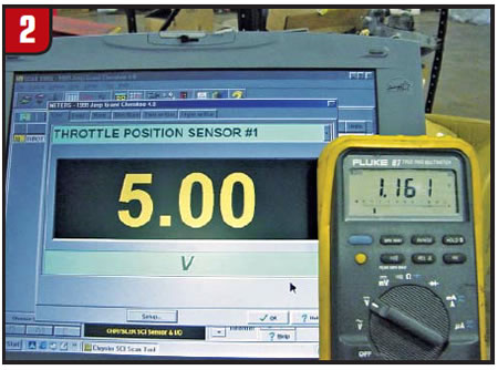
His approach was to check TPS voltage with the scan tool and a voltmeter at the PCM (connector C1, pin #23) with the key on, engine off. The scan tool revealed a whopping 5-volt reading at closed throttle; the voltmeter showed 1.161 volts at closed throttle (Figure 2). So how can this happen?
Chrysler provides the following explanation about how its JTEC PCMs function.
There are more PCM inputs than there are available microprocessor input pins. To accommodate all the required inputs, the microprocessor may receive inputs from two circuits on one pin by using multiplexing. The microprocessor keeps track of which input is being received by the discharging of a capacitor controlled by the PCM’s internal clock. If there is a problem that does not allow the capacitor to discharge (for example, an input shorted to voltage), the PCM may set a DTC for the companion input.
What this means is that when one of the two circuits sharing the same capacitor is shorted to power, it has a malfunctioning effect to the PCM internally with both circuits. This would explain why the computer thinks the TPS is at 5 volts yet when you check it with a voltmeter at the TPS it works perfectly. Often this is misdiagnosed as a bad computer, but after replacing the PCM you quickly learn that it wasn’t the problem.
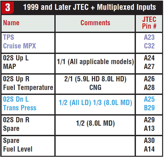
The chart in Figure 3 is quite revealing, as it explains which two circuits are shared inside the PCM. The top column going from left to right with the text in purple reveals how the cruise-control sense wire and the TPS share the same capacitor. So if there is a short to power with the cruise-control sense wire, it also will affect the TPS.
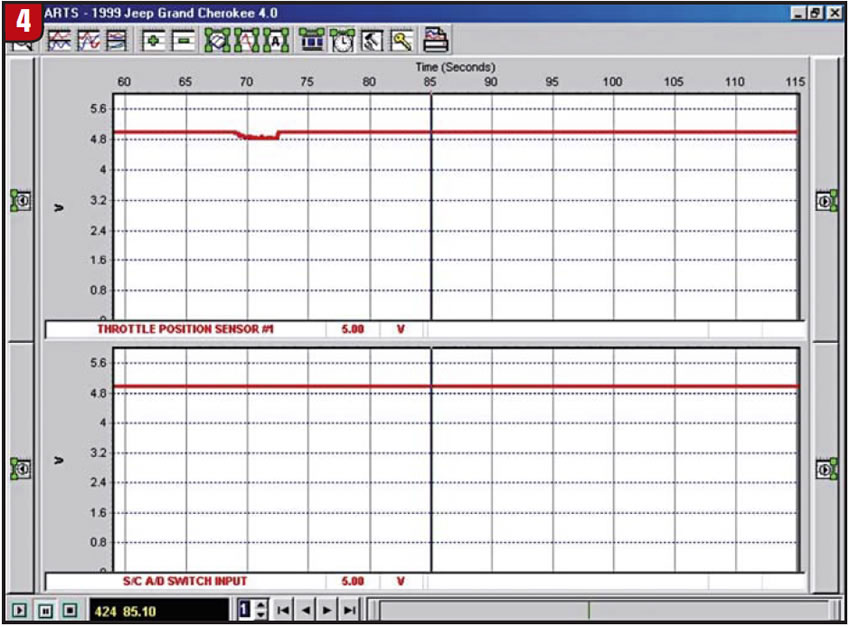
Another question you may be asking yourself is, if the TPS’s shared capacitor circuit (the cruise-control sense wire) was shorted to a 12-volt source (the horn’s 12-volt clock-spring circuit), why wouldn’t the scan tool see 12 volts instead of 5? The reason is that the engineers did not make provisions for that circuit to see voltage higher than 5 volts on the TPS. In fact, both the TPS and the cruise-control sense wire are 5-volt circuits, and if either of them is shorted to anything more than 5 volts, the scan tool will reveal a maximum of 5 volts because it was never meant to see anything more. Figure 4 is the Ease scan tool graphing out these two circuits as the PCM sees them internally, and they are both pegged at 5 volts.
As a side note to this article, looking back at Figure 3, notice the fourth column with the text in blue. When an 02 sensor shorts it affects the governor-pressure sensor with RE-style units. Many times it will be in limp (third gear) with a governor-sensor code, yet there is nothing wrong with the governor sensor or the wiring from the sensor to the computer. This is why you may see a high governor-pressure reading in the scan tool but with a voltmeter on the sensor signal wire observe a voltage indicating 0 psi (0.50-0.60 volt).
Getting back to our problem, since we now know that the cruise-control sense wire shares a capacitor with the TPS, it would be a good idea to acquire a wiring diagram so you can locate and check the voltage on the cruise sense wire at the PCM (Figure 5). When it was checked with a voltmeter at the PCM’s C3-connector terminal 32 (Figure 6), there was a steady 12-volt reading as expected because of the presence of code P1596.
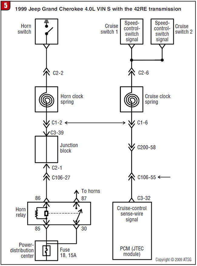
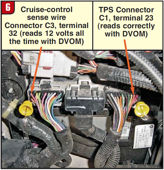
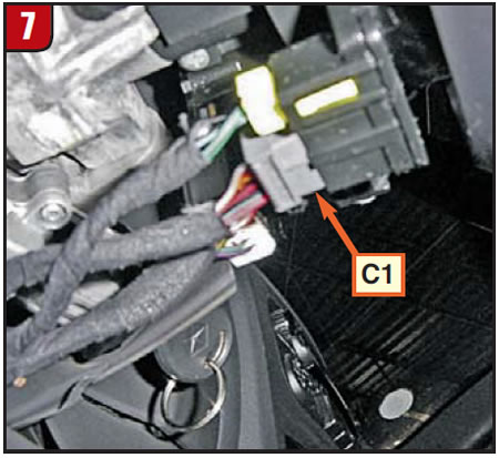
Looking back at the wiring diagram in Figure 5, the potential trouble spots are the clock spring’s C1 connector, connector C200 and C106. With the C1 connector being under the steering column, it was the easiest and quickest to unplug (Figure 7). When it was open, the shorted 12 volts to the cruise input switch disappeared and the TPS went back to a normal voltage on the scan tool. This narrowed the problem down to a faulty clock spring causing its 12-volt feed from the relay to be shorted to the 5-volt cruise-control sense wire.
But the question remains, why did this cause no upshift from first gear with some vehicles and no 4th or TCC lockup with others? This is determined by the type of transmission in the vehicle. An AW4 transmission uses shift solenoids for all four gears. If the computer sees a wide-open-throttle signal, such as a TPS at 5 volts, all the time it will never upshift from first gear. But if the vehicle has a 42RE-type transmission (except 2005 and later 48REs with the TTVA), the 1-2 and 2-3 upshifts are not determined by the TPS signal; only 4th and lockup are. The 1-2 and 2-3 shifts are controlled by governor pressure related to speed and a typical mechanical throttle cable.
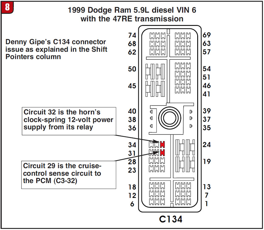
With all three questions having now been answered, I’ll make one final point. Although faulty horn clock springs are the most-common reason for a 12-volt short to occur in the cruise-control sense wire, driving the TPS voltage high inside the computer, do not fall into the habit of being a pattern-failure repair man and poke a clock spring into the steering wheel without any diagnostics. If Denny had done that he would have had the same problem when he was finished. But he took the time to trace the circuit and found a corroded C134 connector, which was remedied by a little cleaning. Apparently, the horn’s clock-spring power from its relay (terminal 32) runs right alongside the cruise-control sense wire (terminal 29), as you can see in Figure 8.
Another connector issue that John Thornton ran across occurred whenever the park lamps were on. If you compare the wiring in Figure 5 with that in Figure 9 you will notice that a 12-volt supply in the parking-lamp and side-marker-lamp circuits passes through connector C106 terminals 53 and 54 right alongside the cruise-control sense wire, C 106 terminal 55.
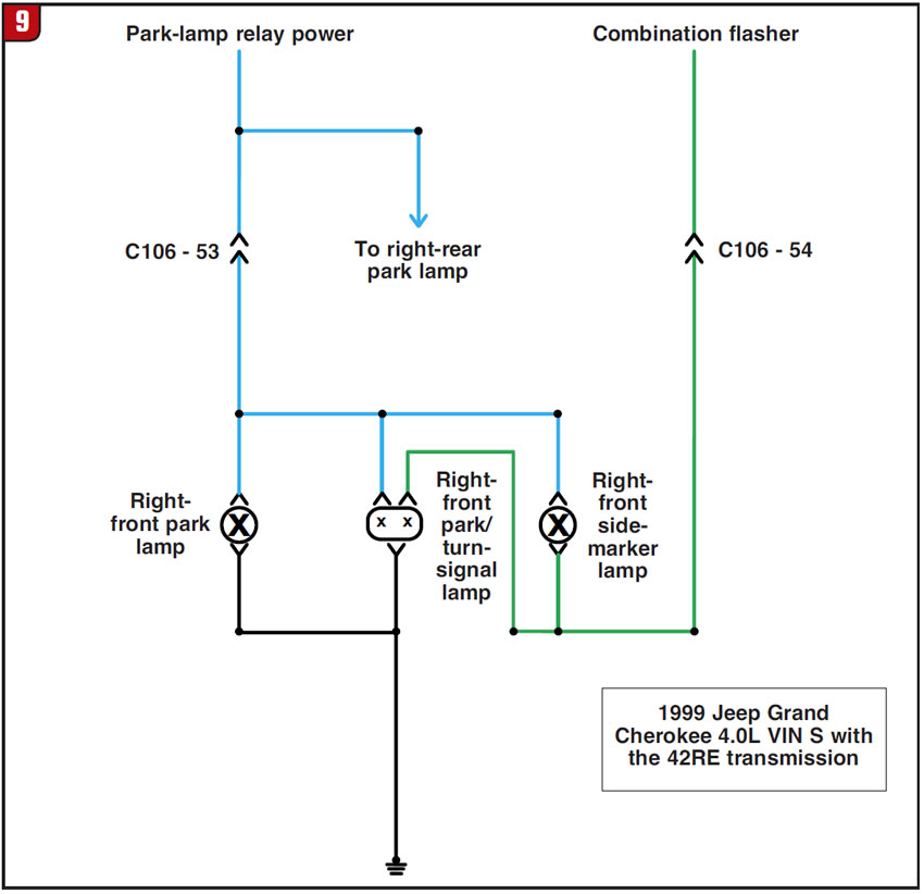
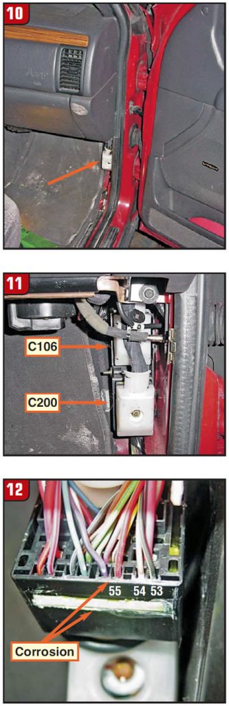
The C106 connector is in the passenger-side foot well (figures 10-12). So here was a short to power into the cruise circuit that had nothing to do with the horn clock spring. It is amazing to see how this cruise-control sense-wire circuit seemed to be routed alongside some form of a 12-volt power source that makes it a potential short area.
If you are interested, figures 13 and 14 provide a wiring and voltage reading of the cruise-control 5-volt sense-wire circuit showing how five inputs are multiplexed to the PCM from the two cruise-control momentary-switch assemblies when it is working correctly.
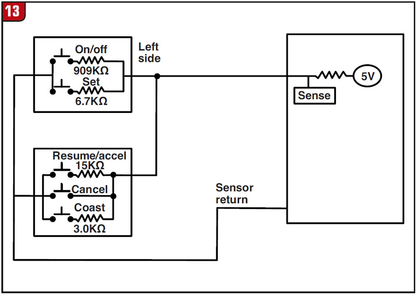
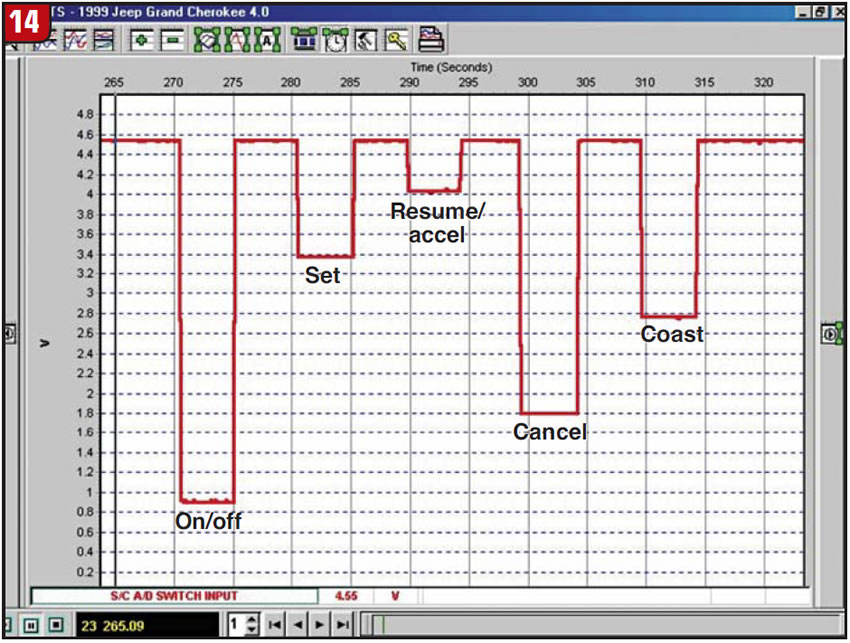
Understanding the multiplexing communication system of these modules goes a long way toward diagnosing odd problems that could potentially mislead you into thinking you have a defective PCM. But now that you have read this, the next time you run into a P0123 code causing shift complaints, you can diagnose it right and toot your own horn!


