TASC Force Tips
- Author: Steve Garrett
- Subject Matter: Component upgrades
First assumptions don’t always turn out to be correct. How many times have you thought you knew what was causing your problem but later discovered it was something completely different — perhaps something you didn’t even consider the first time?
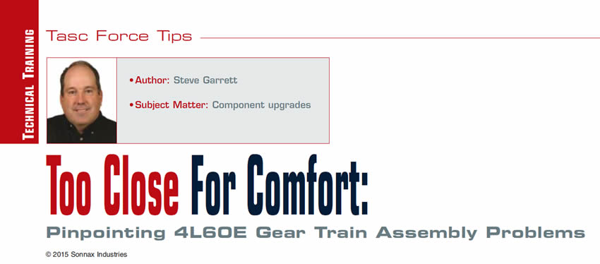
Let’s take a look at a common 4L60/65/70E scenario. During assembly of the transmission, the technician has difficulty installing the output shaft snap ring (Figure 1), or while checking the input shaft endplay finds that it is too tight or too loose (spec is 0.005″ to 0 .035″). The technician tears the unit back down to inspect for an (assumed) assembly problem, but cannot seem to figure out why the stack-up is not working.
What’s going on here?
Keep in mind that replacement parts are not all the same, even though they may seem to fit. The late-production 4L60E family of transmissions has undergone a number of component updates and changes. Some parts will interchange while others will not, and installing incorrect components often leads to the creation of other problems, such as the one mentioned above.
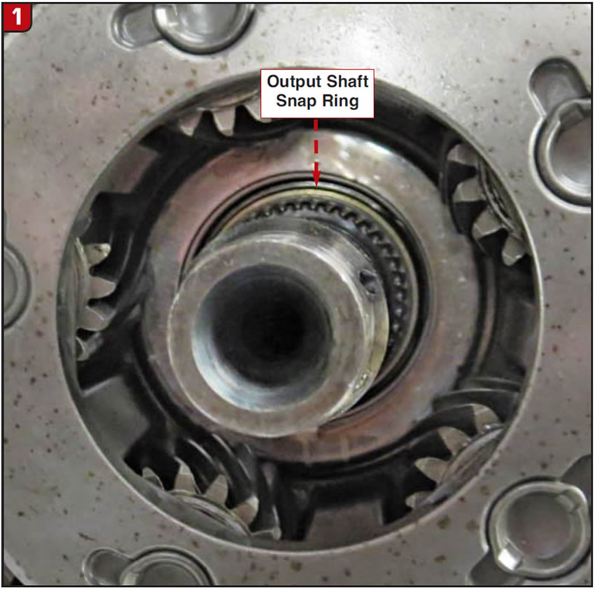
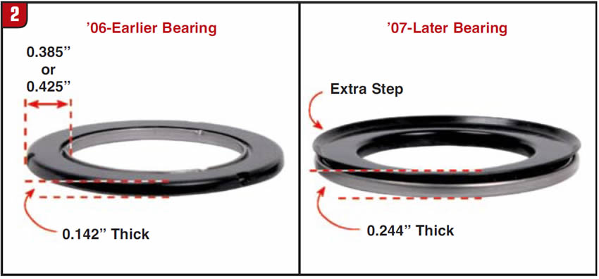
A good example of this is the design update that GM made in March 2007. The reaction carrier bearing was upgraded to a thicker design, and the reaction carrier and shaft were changed to accommodate the new bearing (Figures 2 & 3).
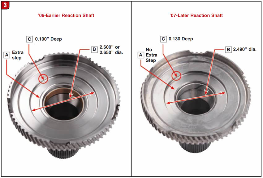

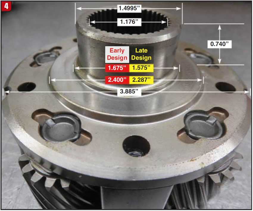
Many builders don’t appreciate that these revisions include both the four- and five-pinion carrier designs (Figure 4). No problems will arise as long as all three components are matched as a set, but if the different designs are mixed, incorrect endplay will result and the output shaft snap ring will not install properly. This is a very common issue, and inspecting/measuring the components prior to installation is an important step to prevent it. Note that some of the dimensions match from carrier to carrier, while others do not (Figure 4). The devil is in these details, and he’ll ruin your day if you let him.
It is easy to verify correct assembly on a 4L60E prior to installing the components in the case. Set up all the planetary components and bearings onto the output shaft in their correct position and order, then install the snap ring inside the front planet to retain the components on the shaft. Position the complete assembly with the sun shell face down on the workbench. A dial indicator or feeler gauge can now be used to check the bench endplay (Figures 5 & 6).
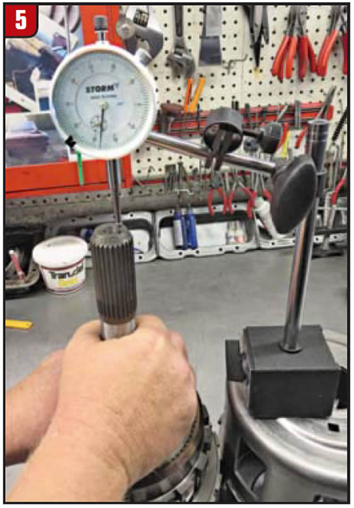
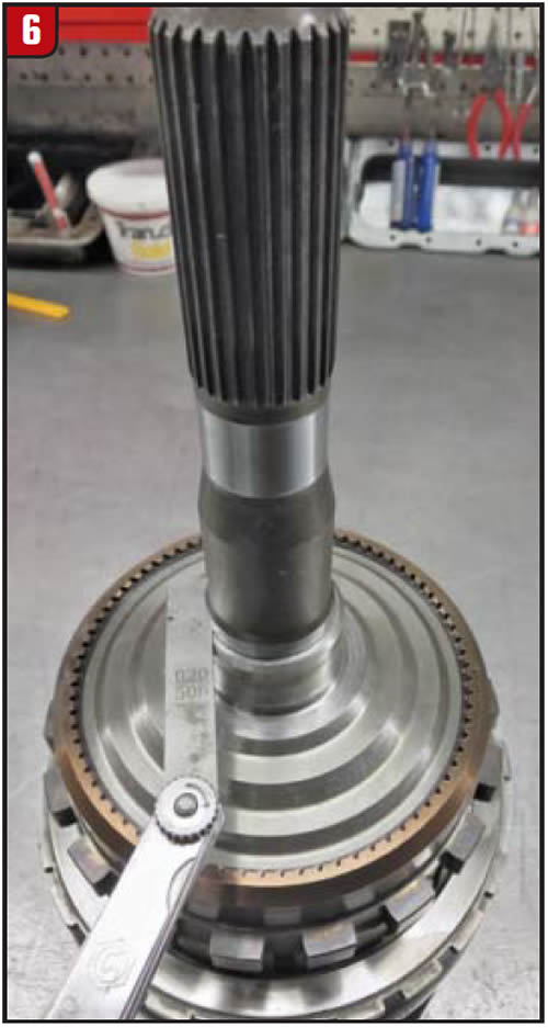
Using either method, the desired outcome will be about 0.020″ to 0.030″, which indicates the stackup is correct. If too loose or too tight, a problem is indicated. To find the offending part, you can pull the assembly apart and reinstall one original component, then reassemble and measure again. If your measurements are still not within spec, that part can be eliminated as a suspect. Now remove that component — be sure to reinstall the new part again in its place — and reinstall another original part, then measure again. Repeat the process of reinstalling one original part at a time and then measuring until the culprit is identified.
As you can see, measuring bench endplay can save you time and frustration. It only takes a minute, and you now have the peace of mind that the new parts you installed will work together without creating new issues.
Steve Garrett is a Sonnax technical specialist and member of the Sonnax TASC Force (Technical Automotive Specialties Committee), a group of recognized industry technical specialists, transmission rebuilders and Sonnax Industries Inc. technicians.


