Up to Standards
- Subject: Diagnosis and repair of front drive axles and differentials
- Unit: GM K series
- Essential Reading: Shop Owner, Rebuilder, Diagnostician
- Author: Mike Weinberg, Rockland Standard Gear, Contributing Editor
With four-wheel-drive and all-wheel-drive vehicles being produced in such huge numbers, these trucks and cars have become an important source of repair business for our industry. Transmissions and transfer cases are now a huge part of the repair and reman market. It is also obvious that these designs use both front and rear differentials to transfer power to both sets of drive axles. This has effectively doubled the amount of differential work that will find its way to the repair shop.
Although the principles are basic to all differential work, the front differentials and drive axles have some unique issues that we will look at here. For the purpose of this article we are reviewing the front drive axles used in GM K-series trucks. The common K trucks are graded by gross-vehicle-weight capability. The K10-series 1/2-ton trucks use an 8.25-inch ring gear with ratios of 3.42, 3.73 and 4.10-1. The 3/4-ton K20 trucks use the 8.25-inch ring gear with ratios of 3.42, 3.73, 4.10 and 4.26-1, and the 1-ton K30 series uses the 9.25-inch ring gear available in ratios of 3.73, 4.10, 4.26 and 5.13-1.
When you’re repairing one of these vehicles, it is important to make sure that the front and rear axle ratios match exactly and to make sure when you are ordering parts for a front drive axle to specify that to your parts vendor, because the front ring and pinion gears are cut for reverse rotation.
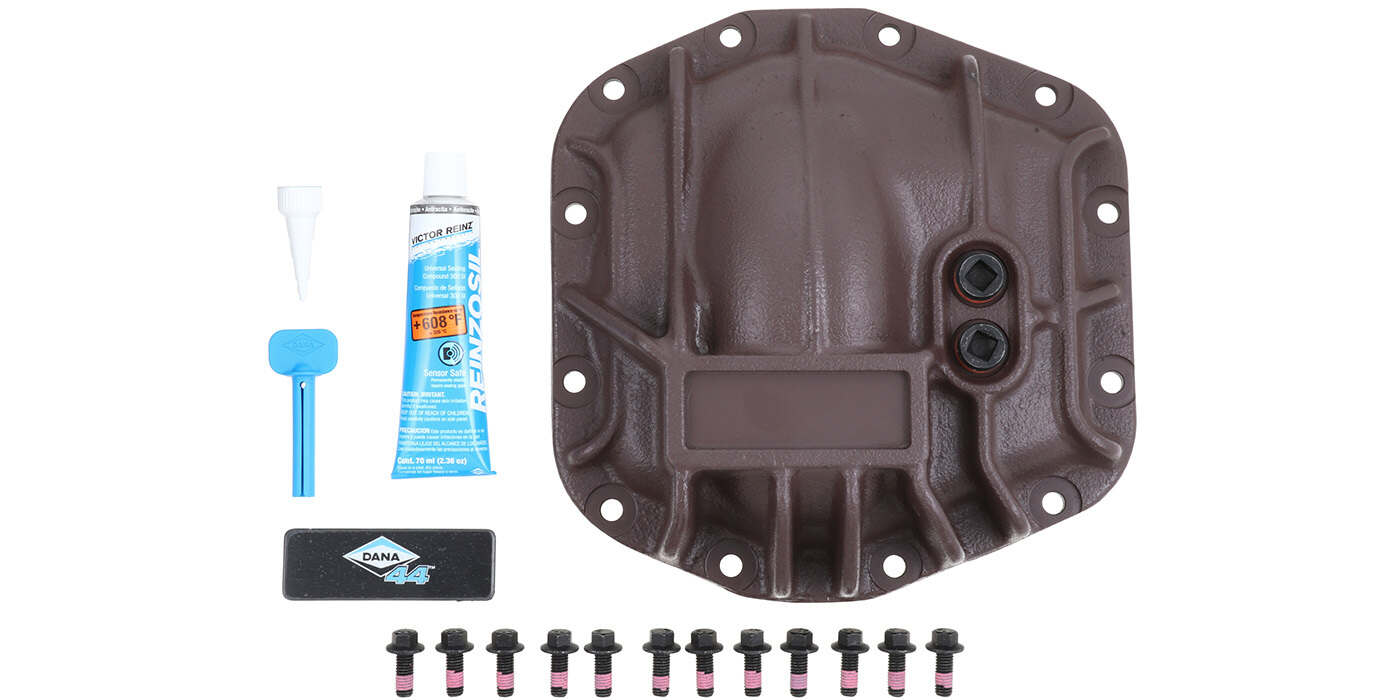
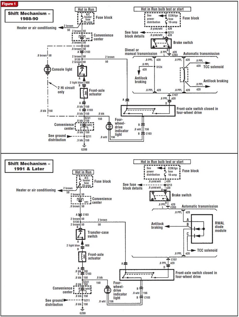
The K-series trucks’ front-drive-axle design uses an aluminum differential case that splits in half for service and contains an electrically operated front-axle disconnect. Proper operation has the front axle disconnected from the drive axle in 2WD, and when the transfer case is shifted to a four-wheel-drive mode, power flows through the 4WD switch on the transfer case to energize the front-axle actuator, which now locks the front axle to the drive axle in the differential to provide four-wheel-drive traction. This is a simple system, but there are many areas that if not understood can create issues for the customer and the shop.
- Whenever removing any axles or driveshafts, match-mark the flanges so that they will be reassembled at the original locations. The vehicle manufacturer balances all these shafts and flanges during assembly, and noise, vibration and harshness (NVH) will result from reassembly in an out-of-balance position.
- Shifting into 4WD mode will engage the transfer case, and there will be a short delay before the front axle is engaged. This delay is normal, and cold temperatures can increase the delay. When the system is in 4WD with the front axle locked, the 4X4 status light should turn on.
- If the vehicle is shut off in 4WD, the front axle can disengage into 2WD. When the engine is restarted, the unit will re-engage 4WD with the same short delay.
- These units can shift into 4W High “on the fly” (while moving). These units also will be hard to shift into 4WD while stationary because of lack of motion in the meshing parts resulting from lack of spline or gear match. Putting the vehicle into motion should make the shift to 4W High easy.
- If you shift into 4 High while parked, the 4WD status light usually will not turn on until the vehicle begins to move and gear mesh is obtained.
- During the shift from 4WD to 2WD the 4X4 status light may remain on because of spline lock of the front-axle components. Releasing the gas pedal and then going back to throttle usually relaxes the components enough to release. At slow or stopped speeds it may be necessary to stop and reverse direction for a few feet to allow the components to disengage.
- Because the axles turn at different rates during turns, it is NEVER advisable to drive these vehicles in 4WD mode on dry pavement.
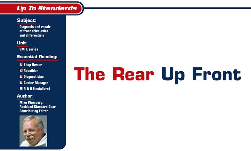
Another issue on the K-series front drive axles that generates a great deal of confusion and technical-hotline calls is the electric axle shift-actuator motor. The 1988-90 models used a screw-type drive motor to engage the front axle, which was equipped with a two-wire connector and had a silver body tube. In 1991 the design was changed to reduce engagement delay, and a black-bodied, three-wire “thermal gas-charged actuator” was introduced.
Unfortunately, the package included no installation instructions. The following will give you the proper way to hook up a three-wire system when replacing a two-wire actuator. There are two brown wires and one black or blue wire. The short brown wire goes to the positive side of the transfer-case switch. The long brown wire goes to ignition on, and the black or blue wire goes to ground.
Caution: If you wish to test the three-wire black-bodied actuator by supplying 12 volts to it, do so only when it is installed properly in the front-axle case. If you put 12 volts to this unit while it is removed from the front-axle housing, it will be ruined and no good things will happen to anyone who is standing in front of it, and the guy who is holding it usually will have to change his shorts.
These 4WD systems involve many parts. We have the rear differential and axles, the rear driveshaft, the transfer case, the front-axle driveshaft, and the front axle and differential. NVH (noise vibration and harshness) problems are always the most difficult to diagnose and a real cause of customer complaints. A bad day generally starts with the customer saying, “It wasn’t like that until you worked on it.”

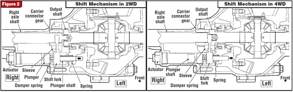
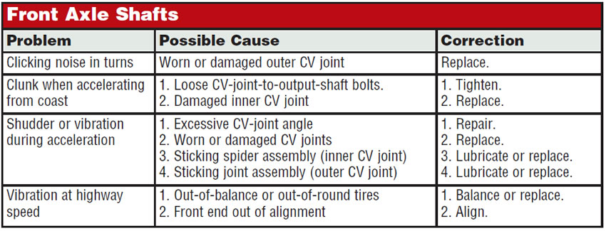
I have enclosed here a pretty comprehensive factory guide to solving these problems, but you can prevent many of them by rigidly following your own set of established steps. Verify the customer’s complaint, with the customer along if possible. Drive the vehicle thoroughly in all modes and ranges if possible. Match-mark all flanges, yokes etc. before disassembly. Remember that there are no unimportant parts on the vehicle and that the manufacturer will not go to the trouble of developing and attaching components to any system just to make more work for you. Do not leave off any parts that were removed. All weights, baffles, shields, clips, grommets, bushings etc. must be in their proper location and in good condition for the system to function correctly and quietly and without vibrations being transferred into the cab.
The front differential’s ring and pinion are the same as those of the rear axle except that they rotate in the opposite direction. The same rules apply to repairs such as replacing a ring and pinion or bearings. Pinion depth and pinion- and ring-gear backlash need to be set according to the factory specs as you would in any differential repair. A couple of items not included in the factory diagnostic guide for front differentials follow:
Low-speed knock generally is caused by worn universal joints or play in the differential side gears caused by an oversize side-gear counterbore.
Backlash clunk is defined as excessive clunk on acceleration or deceleration. Common causes are excess ring-and-pinion backlash, worn thrust washers, worn teeth on side gears and pinions, excess clearance between case counterbore and side gears, axle and side-gear spline wear, worn case, and a bad or worn-out rear-axle pinion shaft.
These units are money makers if you invest the time to learn how they work and establish good diagnostic routines. Be sure to inspect all related parts carefully, as they affect proper operation just as much as the transmission and transfer case.