Torque Converter Tech Tips
- Author: Ed Lee
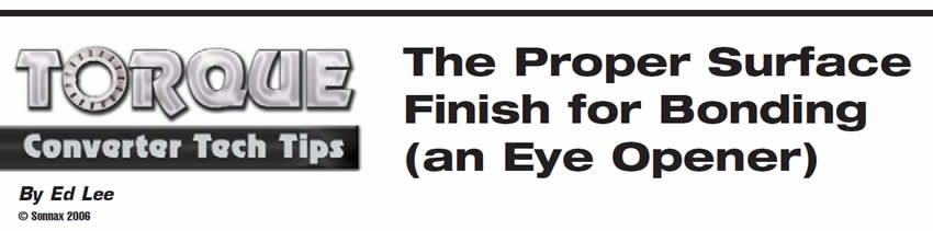
Choosing the correct surface finish for bonding can be controversial. Some rebuilders claim you can bond to a surface as smooth as glass, provided the bond-line temperature and the compression pressure are correct. Others claim that a very rough surface finish is needed for a good bond. The finish of a machined surface is rated on a roughness-average (RA) scale.
Figure 1 shows an average of the peaks and valleys of the machine cut. The higher the number, the rougher the surface finish; the smaller the number, the smoother the surface finish.
A large amount of time and money has been spent over the years to find the best possible surface finish for a good bond. This expansive testing proved that a surface finish of 90 to 120 RA was the best range for bonding. A different test done at a later time backed up the original test. This new test proved that the standard-thickness adhesive would not penetrate to the bottom of the machined groove if the RA was more than 135.
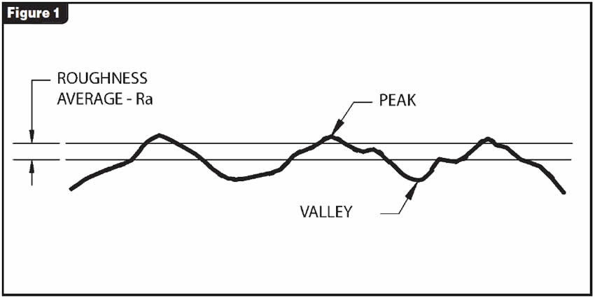
Knowing what the proper surface finish is for a good bond is one thing, but putting this information into practice is another thing altogether. A profilometer is needed to measure the RA of a machined surface correctly. This measuring instrument drags a diamond pointer across the surface and accurately measures the peaks and valleys (see Figure 2).
Unfortunately, the high cost of a profilometer is more than most torque-converter shops can afford. So how does the average technician know whether his bonding surface is 90-120 RA? A machinist will tell you that if you are machining a 10.5-inch-diameter piston, a head speed of 256 rpm and a tool feed of 0.030 inch per revolution or less, with a 1/32-inch-radius tool bit, will give you a surface finish of 90 to 120 RA. The tool bit must have a contact radius that is at least as wide as the width of the machined groove.
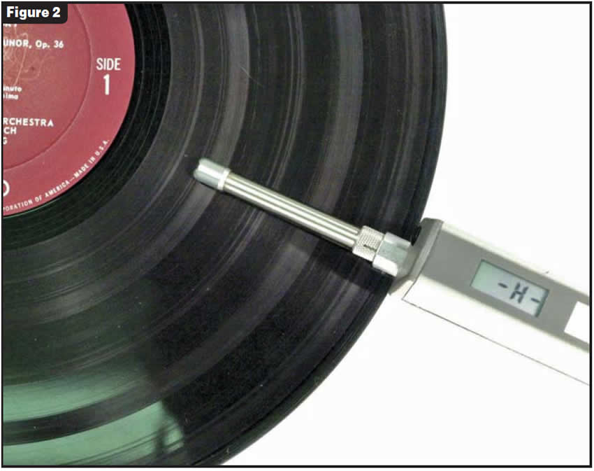
This is great advice for a machinist, but for the average machine operator in the average torque-converter shop, this advice isn’t that helpful. The most-widely accepted practice is to make the bond surface like a phonograph record. This would be great advice if a phonograph record had a surface RA in the 90-120 range. Unfortunately, when the surface finish of Tchaikovsky’s 4th Symphony in F minor was checked with a profilometer, the dial went off the scale (see Figure 3).
That meant that the surface finish was rougher than 200 RA. A TC piston that looked rougher than the record was checked, but it had an RA of 180. This was better than the record but still too rough for bonding.
A more down-to-earth method for checking surface finish is to use a “surface-finish comparator” (see Figure 4).
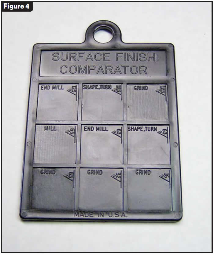
A plastic version is available in the Manhattan Supply Catalog “MSC” for less than $9 (Part No. 06558118). This comparator has RA finishes that range from 16 to 500. The 63-, 125-, 250- and 500-RA finishes compare the same RA finish machined with four different processes. This is especially helpful with the late-model front-wheel-drive Chryslers that are too hard to machine and must be ground. With the comparator, you can do a side-by-side thumbnail comparison or a side-by-side visual comparison with a handheld magnifying glass.
Special thanks to Chris Horbach of Raybestos for his technical assistance in writing this article and to Irv Gers for the loan of his record.

Ed Lee is a Sonnax technical specialist who writes on issues of interest to torque-converter rebuilders. ©Sonnax 2006


