Up To Standards
- Author: Mike Weinberg, Contributing Editor
Electronic Operation and Diagnosis
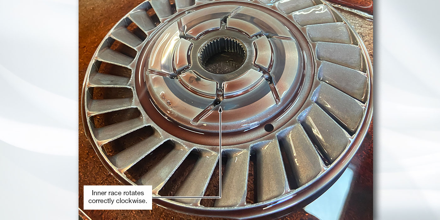
In last month’s article we looked at the mechanical operation of the BorgWarner 44-11 automatic all-wheel-drive transfer case, which replaces the BW 44-05 transfer case and is used in the Ford Explorer, Ranger and Mountaineer and Lincoln Aviator models. This month’s article is devoted to the electronic functions of this transfer case.
The mechanical end of the transfer case is relatively simple, and the design did not change much; however, the electronic and computer controls are advancing at a rapid pace, and this is the area where most shops have trouble. In the repair manual you will find 29 pages devoted to repairing the transfer case and more than 100 pages covering diagnosis and testing for the electronic control systems. It is absolutely impossible to diagnose or test one of these units electrically without a service manual.
That said, it is also crucial to your success to stop looking at the transmission or transfer case as a unit and begin to visualize it as part of a vehicle composed of interlocking control systems. Once you start to think of the vehicle as a collection of related systems, you open your mind to possibilities that affect the unit you are working on but may have nothing to do with the parts inside the unit. It is important to step back and view the forest and not just the trees.
In the earlier BW 44-05 you have an “active” transfer case that is capable of sending torque to the axle that needs it according to changing conditions. The BW 44-11 is very much the same design with more-sophisticated electronics.
“Why does it have to be more complex?” you ask, figuring that the engineers are changing things just to keep their jobs and make yours tougher. Look at the vehicle systems and you will see a lot of added sophistication. We now have four-wheel antilock-braking systems (ABS), which affect the torque biasing on the transfer-case clutch. There is now a “stability” system, which is a form of traction control that is designed to make the SUV platform with its high center of gravity safer for the average American driver to use.
This system will also affect the computer controls that make the transfer case function. To design and perfect this package. the engineers have had to add more computer control, and more computer control creates the need for increasingly complex diagnostic routines and the need to look at circuitry that is not directly connected to the transmission and transfer case.
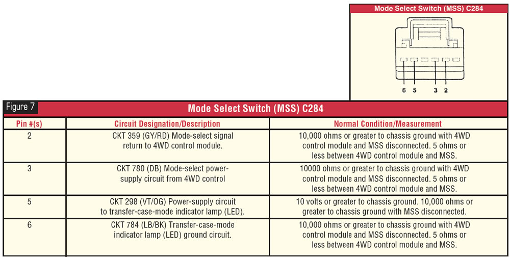
The electronic parts that control the transfer case are basically the same as those in the BW 44-05. An electric shift motor mounted on the transfer case engages the various modes of operation. Contained in the motor is a surface-contact plate or “encoder” that tells the computer which position the motor is in. In the passenger compartment is a mode-select switch (MSS) that enables the driver to select the transfer-case operating modes, which are 4×4 Auto, 4×4 High and 4×4 Low. On the 2003 models, the MSS will light up only when the unit is in 4×4 Low. A brake-pedal-position (BPP) sensor informs the 4WD control module whether the brakes are being used.
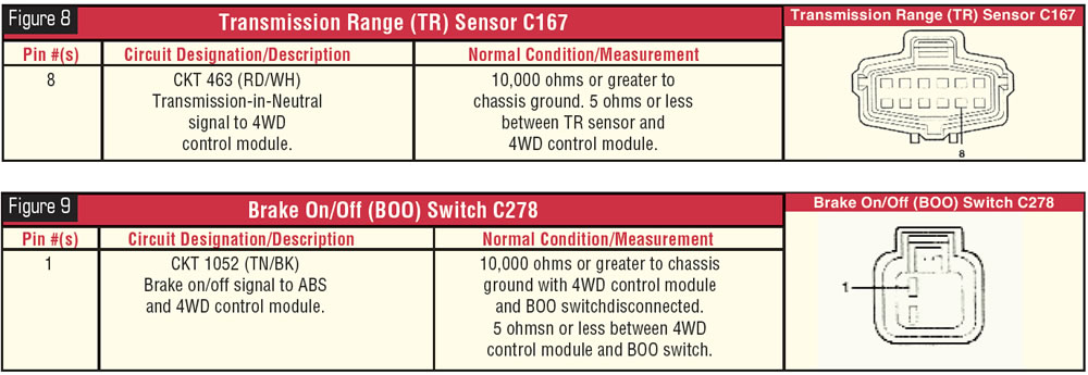
On the transmission (automatic) is a digital transmission-range (TR) sensor that tells the powertrain control module (PCM) which range the transmission is in. Manual-transmission models have a clutch switch that tells the computer when the clutch is depressed. The throttle-position sensor informs the PCM what the throttle opening is. The PCM will change the throttle-position signal into a pulse-width-modulated (PWM) signal and transmits that signal to the 4WD control module, which uses that signal to control and modulate the transfer-case clutch-apply cycle.
Mounted on the transfer case are the output-shaft-speed (OSS) sensors, which transmit the speeds of the two driveshafts to the 4WD control module. The computer then uses the difference between the two shaft speeds to regulate the duty cycle of the transfer-case clutch pack. One difference in the BW 44-11 electronic system is that vehicles equipped with stability assist have the speed sensors mounted on the transfer case but the sensors are not used. With stability assist, the wheel-speed sensors send the signal to the stability control module, which then transmits the signal to the 4WD control module to vary the clutch duty cycle. The vehicle speed sensor now receives its signal from the ABS, and that signal is sent to the 4WD control module to let it know how the vehicle road speed.
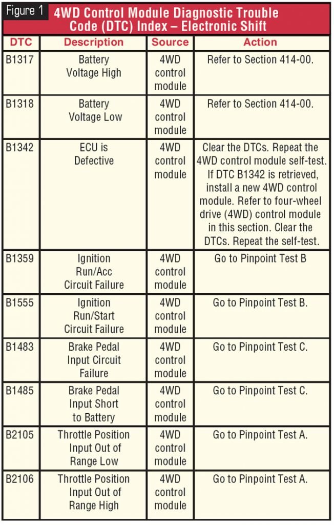
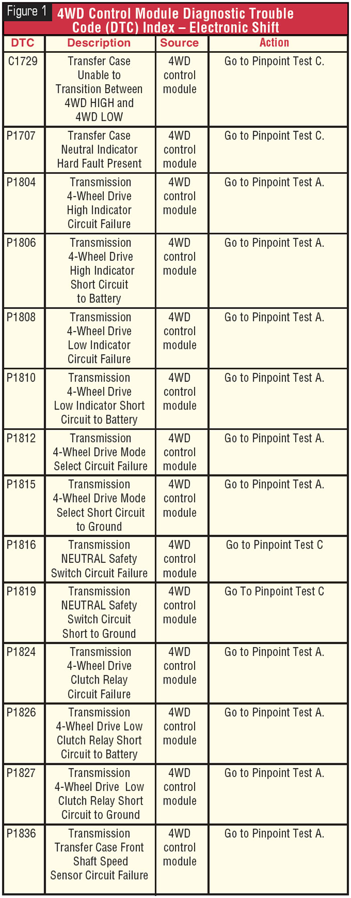
As you can see, with all this information being provided to the 4WD control module from different interlocking systems, there is much more involved in diagnosis than just the transfer case. There are four types of DTCs that will show up on a scan tool: B, C, P and U codes. The chart in Figure 1 is a code index for your use.
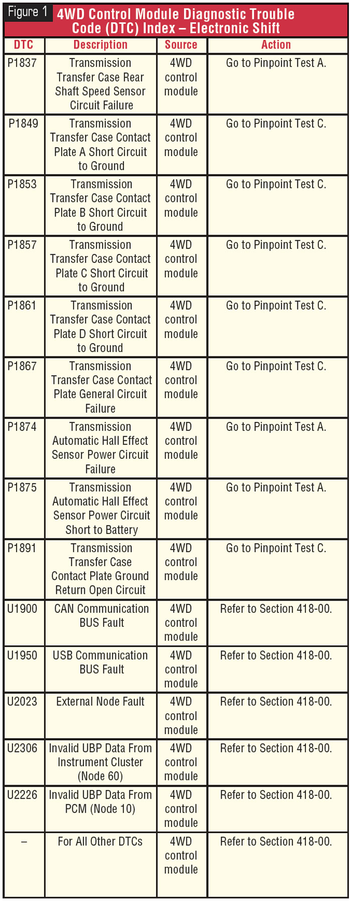
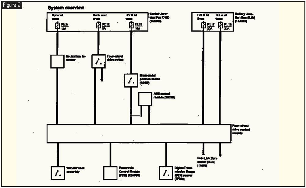
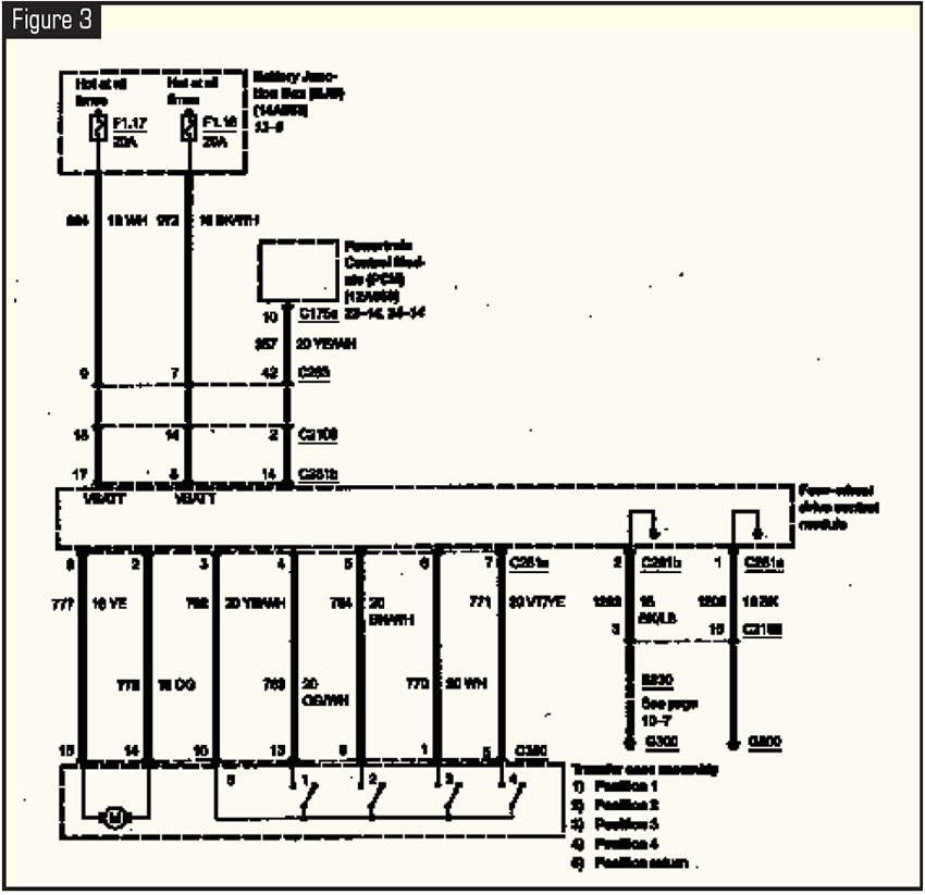
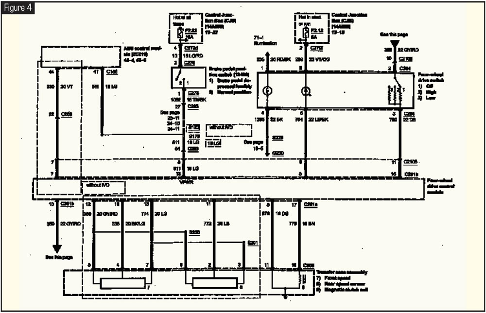
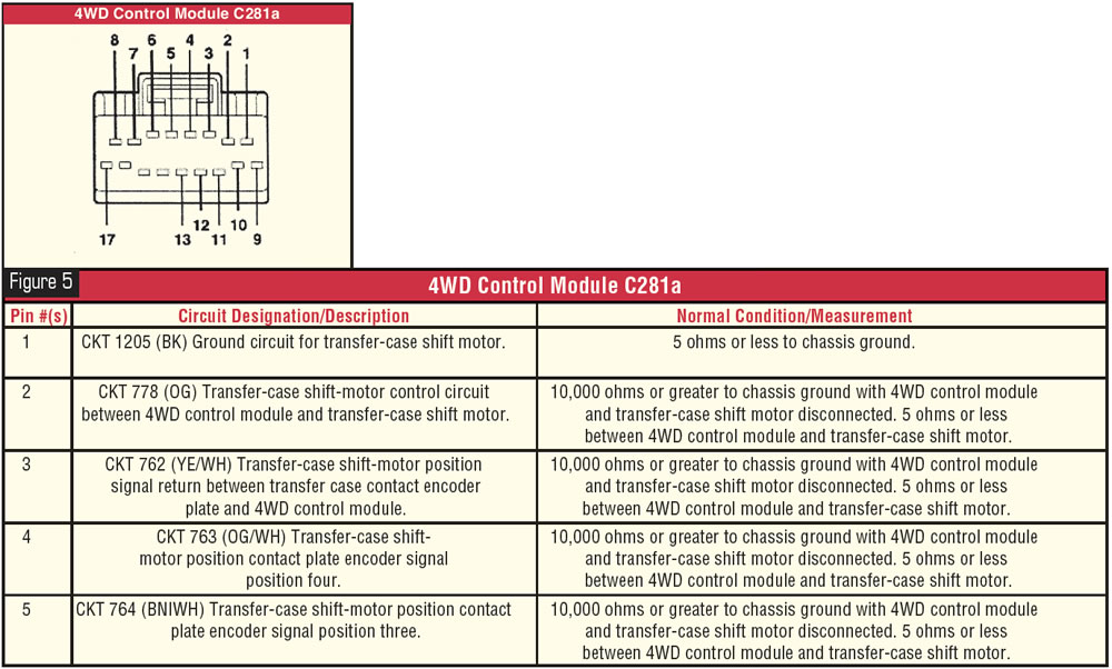
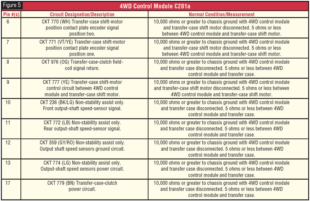
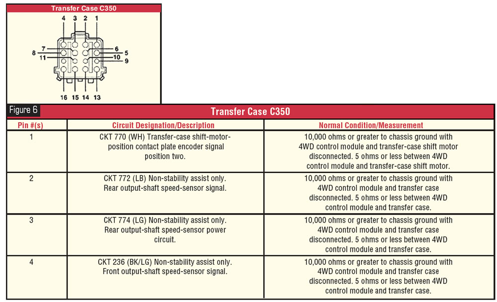
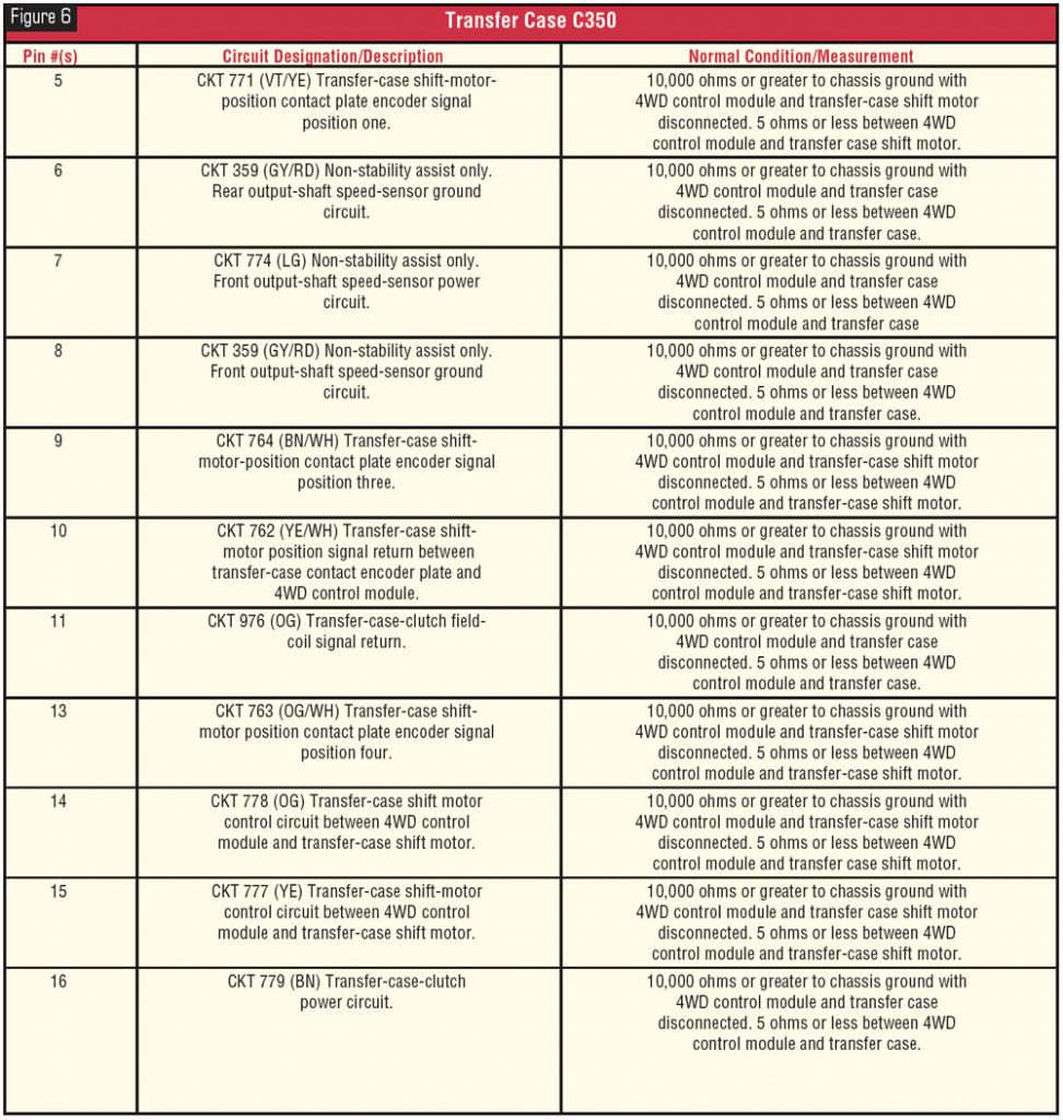
Also included are the various wiring diagrams and circuit descriptions (see figures 2-9) for the circuitry involved. Although diagnosis has become more complex, the diagnostic programs have improved dramatically, with the appropriate scan tool being able to activate the circuits to measure performance as well as download DTCs and other information. To be sure of what is creating the customer complaint, a thorough examination of the vehicle will be necessary, starting with tire size and pressures and including a proper electronic scanning routine.
There are no more shortcuts to success. Without the proper manuals and diagnostic tools, there will be very few vehicles you can repair quickly and correctly.