
Technically Speaking
- Author: Wayne Colonna, Technical Editor
With the 722.6 being a transmission that shifts from clutch to clutch, smooth shifting requires proper shift overlap. To accomplish this task, a number of components and strategies merge to allow for adaptation under various driving conditions. To fully appreciate what it takes to make for correct shift timing and shift feel, it is good to look at and understand these components and strategies independently. And after having a basic understanding of them, one can see how they work together like members of a musical band to harmoniously accomplish the task at hand.
Hydraulics
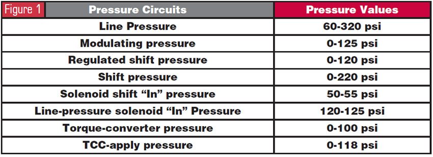
One of the difficulties a transmission technician faces when working with a 722.6 transmission is the absence of pressure taps. Hydraulic pressures are calculated from input signals such as engine torque, engine speed, accelerator-pedal position, cruise-control request, wheel speed, traction status, kick-down switch, selector-lever signal and the program-select switch W/S. If taps were available, there are basically eight different pressure categories (see Figure 1) with their respective range specifications.
Shift Solenoids
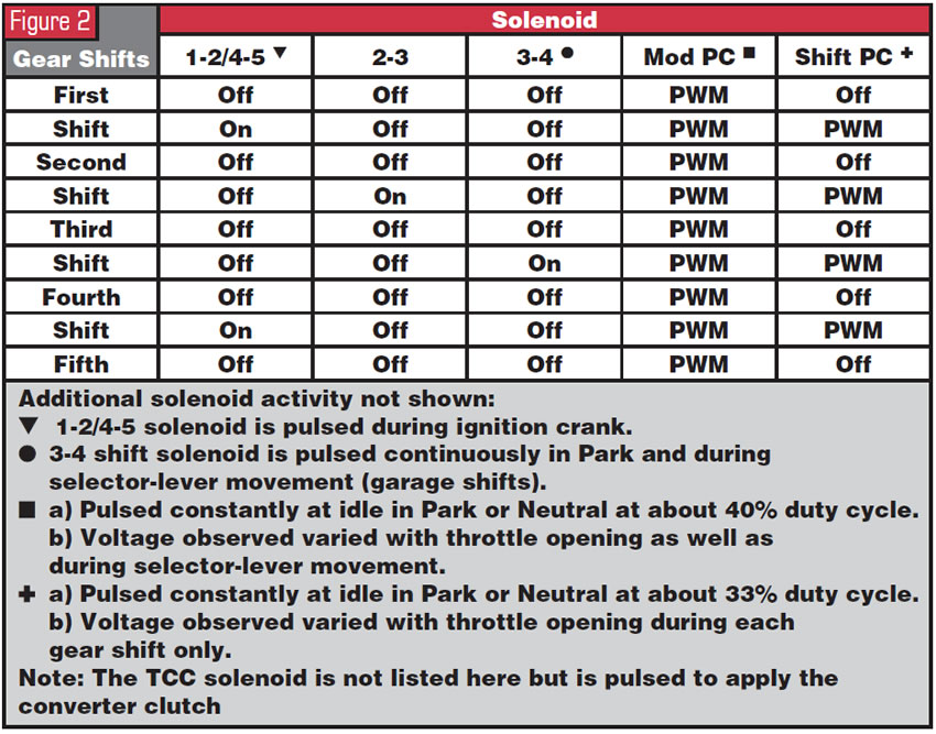
There are three shift solenoids, the 1-2/4-5 (Y3/6y3), the 2-3 (Y3/6y5) and the 3-4 (Y3/6y4). Just by their very names you can determine their functions. Obviously the 1-2/4-5 solenoid is responsible for the 1-2 and 4-5 upshifts and their respective downshifts. Then, of course, you have the 2-3 solenoid for the 2-3 and 3-2 shifts, and the 3-4 solenoid handles the 3-4 and 4-3 shifts. Each of these three solenoids is fed with 50-55 psi of pressure called “solenoid shift pressure,” which is controlled by the shift-solenoid “in” pressure valve.
Pressure Solenoids
There are two pressure-control solenoids. One is called the modulating pressure-regulating solenoid (Y3/6y1) and the other is the shift pressure-regulating solenoid (Y3/6y2).
The modulating PR solenoid regulates pressure between 0 and 125 psi, which influences the pressure-regulator valve to increase main line pressure (working pressure) from a static 60 psi to as high as 320 psi depending upon torque input. This modulating PR solenoid oil also influences the 1-2/4-5, 2-3 and 3-4 shift-overlap valves so that the shift overlap of releasing and applying clutches corresponds to torque input.
The shift-pressure solenoid regulates pressure between 0 and 120 psi, which influences the shift-pressure regulator valve for a controlled clutch-apply pressure (shift pressure) during a shift transition only. This transitional clutch-apply pressure (shift pressure) ranges from a low 0 psi to as high as 220 psi depending upon torque input.
Both of these solenoids are fed with a maximum of 125 psi from the line-pressure-solenoid “in” pressure valve.
Solenoid Shift Chart
As a reminder for those of you who have read past articles on the unique solenoid shift pattern this unit has, you will notice from the solenoid shift chart in Figure 2 that shift solenoids 1-2/4-5, 2-3 and 3-4 are toggled on/off to make their respective shifts. While the unit is in the gear they control, they remain off. This explains why when the computer system observes a fault while the vehicle is being driven, the transmission fail-safes to whichever gear it was in at the time. When the vehicle is brought to a stop and the ignition is cycled, the transmission will remain in second gear.
Shift Groups
By viewing the mechanical, hydraulic and electrical operation of a shift, you can observe that a specific solenoid and a group of valves, described as a “shift group,” cause a change in clutch application. A shift group has two phases. The transition from one gear to the next is called a “shift phase.” The second phase, once the shift is complete and the transmission is in gear, is called the “stationary phase.” Three shift groups achieve five forward speeds. In a shift phase, a shift solenoid initiates the application of one group of valves to change the clutches required for that shift. During this time the other two groups remain in the stationary phase.
The three shift groups are:
K1/B1 (gear changes 1-2/4-5)
This group, which controls the upshifts and downshifts 1-2/2-1 and 4-5/5-4, consists of:
• K1 clutch
• B1 brake
• 1-2/4-5 command valve
• 1-2/4-5 holding pressure shift valve
• 1-2/4-5 shift pressure shift valve
• 1-2/4-5 overlap valve
• 1-2/4-5 shift solenoid (Y3/6y3)
K2/K3 (gear change 2-3)
This group, which controls the upshift and downshift 2-3/3-2, consists of:
• K2 clutch
• K3 clutch
• 2-3 command valve
• 2-3 holding-pressure shift valve
• 2-3 shift-pressure shift valve
• 2-3 overlap valve
• 2-3 shift solenoid (Y3/6y5)
K3/B2 (gear change 3-4)
This group, which controls the upshift and downshift 3-4/4-3, consists of:
• K3 clutch
• B2 brake
• 3-4 command valve
• 3-4 holding-pressure shift valve
• 3-4 shift-pressure shift valve
• 3-4 overlap valve
• 3-4 shift solenoid (Y3/6y4)
Computer Strategy
In the beginning of the article, the section under the heading “Hydraulics” mentioned how internal transmission pressures are controlled and calculated from various inputs to the TCM. The TCM uses these inputs to achieve proper shift timing and shift feel under diverse driving conditions through four basic adaptation programs: driving style, shift time, fill pressure and fill time.
Driving Style
This program is ready to adapt to the driving condition as it happens. The TCM constantly monitors vehicle speed and throttle opening as well as the rate of change of the throttle as it opens and closes. It also looks at lateral acceleration, which is a term for curve recognition. Basically, it monitors wheel speeds to determine when the vehicle is in a turn. In addition to these inputs it also monitors the frequency of gear changes. As a result, it can adapt quickly to a shift time and feel appropriate for the present condition. This adaptation, not written to memory, is known as an adaptation that “lives for the moment.”
Shift Time (Shift Overlap)
This strategy focuses on the quality of the upshifts and downshifts under both load and no-load conditions. Shift-time adaptation gives the TCM the ability to electronically alter the time it takes to go from one gear to another; in other words, the time it takes to disengage one clutch while applying another. Once the TCM has calculated the type of shift that needs to take place, the TCM uses the following two strategies to accomplish the task.
Fill Pressure (Apply Pressure)
This strategy gives the TCM the ability to control and modify the pressure used to engage a clutch, which results in the type of shift feel that will occur.
Fill Time (Preload Pressure)
This strategy gives the TCM the ability to control the time it takes to fill a clutch drum, bringing the clutch pack to a zero clearance but not yet applying the clutch. This adaptation compensates for wear of the friction plate.
Scan-Tool Diagnosis
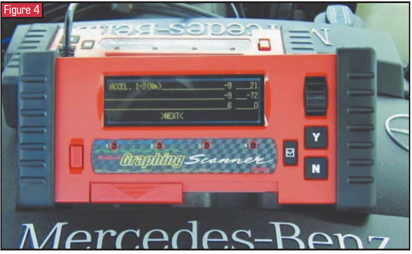
Shift-Time Adaptation (figures 3 & 4)
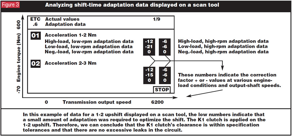
Specific values are needed to make the shift-time adaptation, and these values are written to memory, enabling the ETC to adapt during the following shift occurrences:
- Accelerating-upshift adaptation: Upshifts that occur under load
- Deceleration-upshift adaptation: Upshifts that occur under no load
- Accelerating-downshift adaptation: Downshifts that occur under load
- Deceleration-downshift adaptation: Downshifts that occur under no load (i.e., coast-down shifts)
These values are represented in Newton meters (Nm), meaning torque; in other words, the strength of the shift. There are no ideal numbers to achieve. For example, if a 1-2 upshift that occurs under load with an eight-cylinder engine has a 190-Nm reading and the shift quality is acceptable, one may consider that the computer is able to handle and overcome the existing clutch clearance or a slight leak in the system without a flare on the shift and possible premature damage to the applying clutch. A zero number indicates that a clutch pack does not require adaptation or the clutch pack has not yet adapted. However, if an adaptation value is at its maximum and the shift is unacceptable, repair work may be required. Additional adaptation cannot be achieved when the following maximum values are reached:
- 8- and 12-cylinder engines + or – 210 Nm
- 6-cylinder engines + or – 180 Nm
- 4-cylinder engines + or – 150 Nm
Fill Pressure (figures 5 & 6)
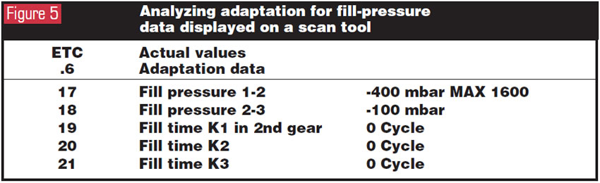
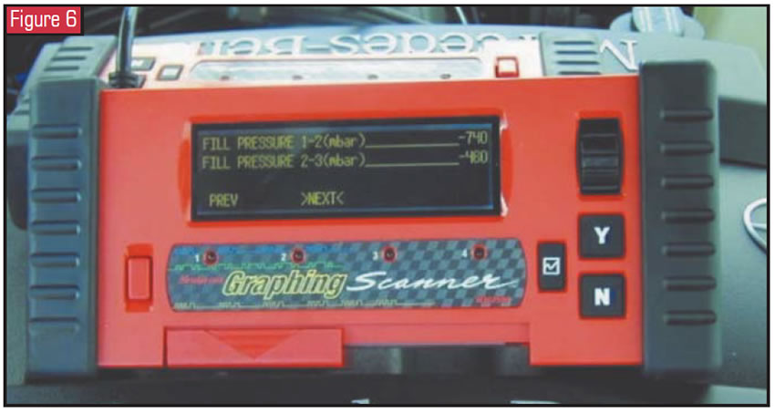
Fill pressure is measured and presented in millibars (mbar). Higher values indicate that the TCM is increasing fill pressure to produce a firmer shift. Lower values indicate that the TCM is decreasing fill pressure to produce a softer shift. 0 mbar means either that the TCM has not stored an adaptive value or that the shift member does not require correction. A value at the parameter’s upper limit, along with poor shift quality, indicates the need for repair.
Fill Time (figures 7 & 8)
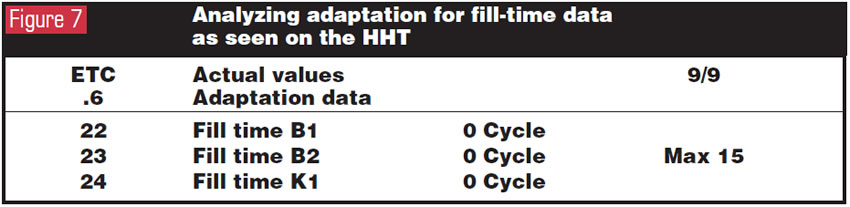

Data parameters for fill time are displayed in cycles of time. The TCM controls the two pressure solenoids with an amplitude-modulated current. Amplitude means the highest value of a periodically varying quantity. The greater the signal amplitude, or difference between the highs and lows of the signal, the greater the pressure. The TCM can change signal amplitude only once per 20 milliseconds (ms). Each cycle displayed by these data parameters equals one 20-ms period. If the scan tool reports a fill-time adaptation of three cycles, this means that it took three periods of 20 ms each (60 ms) to alter pressure enough to accomplish the correct application of the shift member. The maximum fill correction time is 15 cycles, or 300 ms. A value of 0 cycles indicates no fill correction was needed.
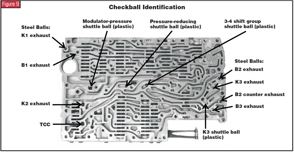
Exhaust Circuits
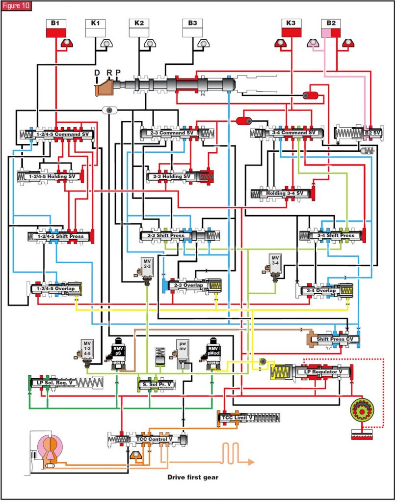
While reading this article you may have asked yourself about the exhausting clutch. There is a shift-overlap valve in the valve body that controls the decrease in pressure of a releasing clutch. In addition, there are checkballs that assist in metering the vented pressure (see figures 9 and 10).
This was just a small glimpse of some of the components and strategies needed to shift a 722.6 transmission. And since this unit does not offer any pressure taps for step-by-step diagnosis, the only eyes a technician has for any diagnosis is a scan tool. And for a scan tool to be of any use, a technician needs to understand the information displayed and have a good overall working knowledge of the transmission’s operation. Otherwise, you may just as well throw a valve body and solenoids on it and see what it does.


