Shift Pointers
- Subject: Differences between Tiptronic and non-Tiptronic versions
- Unit: 4T65-E
- Vehicle Applications: Volvo, Pontiac Grand Prix
- Essential Reading: Rebuilder, Diagnostician
- Author: Carlos Costa
I’m pretty sure that every one of us at some point has met or known of a set of identical (human) twins, and telling them apart can be quite a challenge! If you spend some time with the twins you may be able to distinguish some small, subtle differences between them. Sometimes you have to separate them from each other to see their behavioral differences.
In this article I’ll share with you some of the differences that I have found between the 4T65-E “Tiptronic” and the typical “non-Tiptronic” 4T65-E.
First, let’s talk about how the “Tiptronic” works: The vehicle’s instrument panel will indicate “D” when the shifter is in the normal forward driving mode. When the shifter is moved to the Tiptronic position, the instrument panel will display the TCM-commanded gear appropriate for the speed the vehicle is traveling. For example, if the shifter is moved to the Tiptronic position while the vehicle is in fourth gear (50 mph), the instrument panel will display “4” to indicate to the driver the current commanded gear. The transmission is now in the “tip-up & tip-down” mode, which allows the driver to have control over shift timing.
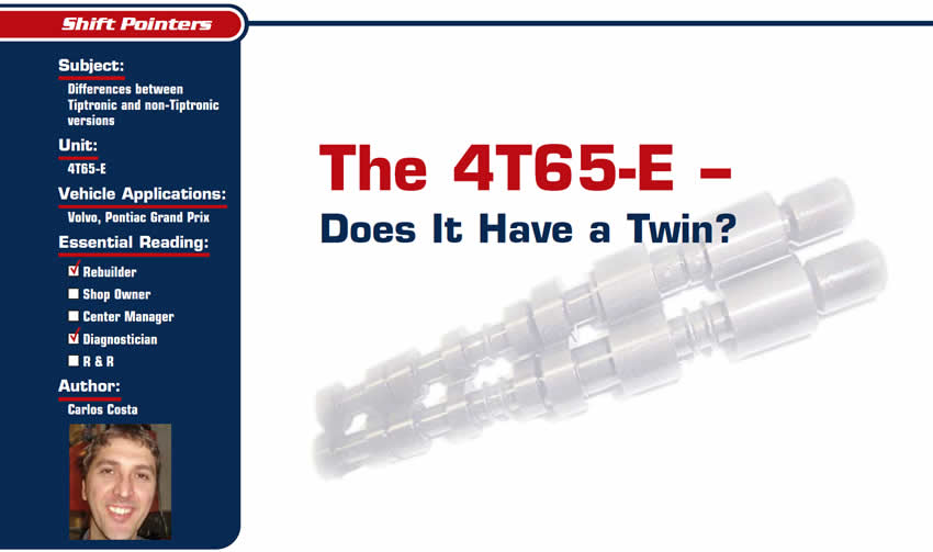
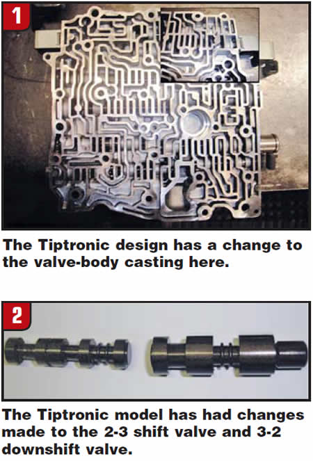
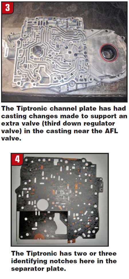
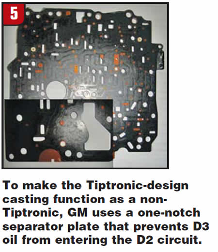
It is noteworthy to add that when the shifter is moved from the D position to the Tiptronic position, the shifter cable will physically move the manual valve to the D3 position. I know what you’re thinking, but it’s true; in the Tiptronic mode you will have access to first and second with engine braking and to third and fourth gears with the manual valve still in the D3 position. This is accomplished by the modifications made to the valve-body casting (Figure 1), 2-3 shift valve, 3-2 downshift valve (Figure 2), channel-plate casting (Figure 3) and the use of the correct separator plate (Figure 4).
It must have notches!
The 4T65E Tiptronic-type valve body & channel plate will work with either a one-notch or two-notch separator plate. If a one-notch separator plate is used, the transmission will function as a non-Tiptronic. Note: The correct plate must be used with the correct vehicle floor shifter.
Figure 5 shows a picture of a “one-notch” separator plate that also can be used with the 4T65-E Tiptronic-type valve body and channel plate. When this one-notch separator plate is installed, it disables the tip-up/tip-down function; this unit will now function as a non-Tiptronic transmission. No parts are interchangeable between the “twins.”
This means that you cannot use any of the gaskets, separator plates (without notches), channel plate or valve body that does not have the casting modifications shown in figures 1 and 3 and interchange them with Tiptronic-design castings.
The Tiptronic-style transmissions are not only in the Volvos; you also will see them in the Pontiac Grand Prix. Wayne Colonna from ATSG has made some excellent bulletins to help us identify the differences between the “Tiptronic” and the typical-design “non-Tiptronic” 4T65-E; this is found in the ATSG 2006 white seminar book, pages 31-49.
Let’s look at the changes GM has made to the 2-3 shift valve and the 3-2 downshift valve found in the Tiptronic-style valve bodies. Figure 6 shows these valves side by side, and at a quick glance there are no differences in the lands on the valve (“identical twins”). If you look closer at the valve there are, however, two identifying rings on the Tiptronic-type 2-3 shift valve and two rings on the 3-2 downshift valve. There is one identifying ring on the “typical-type” 4T65-E shift valves. If these valves were put into a valve-body tray, and both 2-3 shift and 3-2 downshift valves were touching each other, this would give the technician the illusion that the replacement Sonnax shift valves, part numbers 84754-36K and 84754-37K, were identical to the Tiptronic-style 2-3 and 3-2 shift valves. Sonnax does not recommend that its 2-3 shift and 3-2 downshift valves be used in the Tiptronic-style valve bodies. Notice the small picture at the bottom of Figure 6; when the “twins” are separated you can then see where they are different.
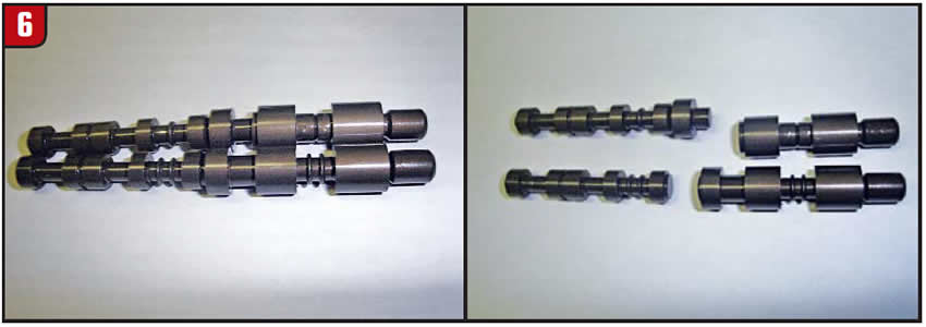
Figure 7 shows a partial schematic with two colored lines through the valve.
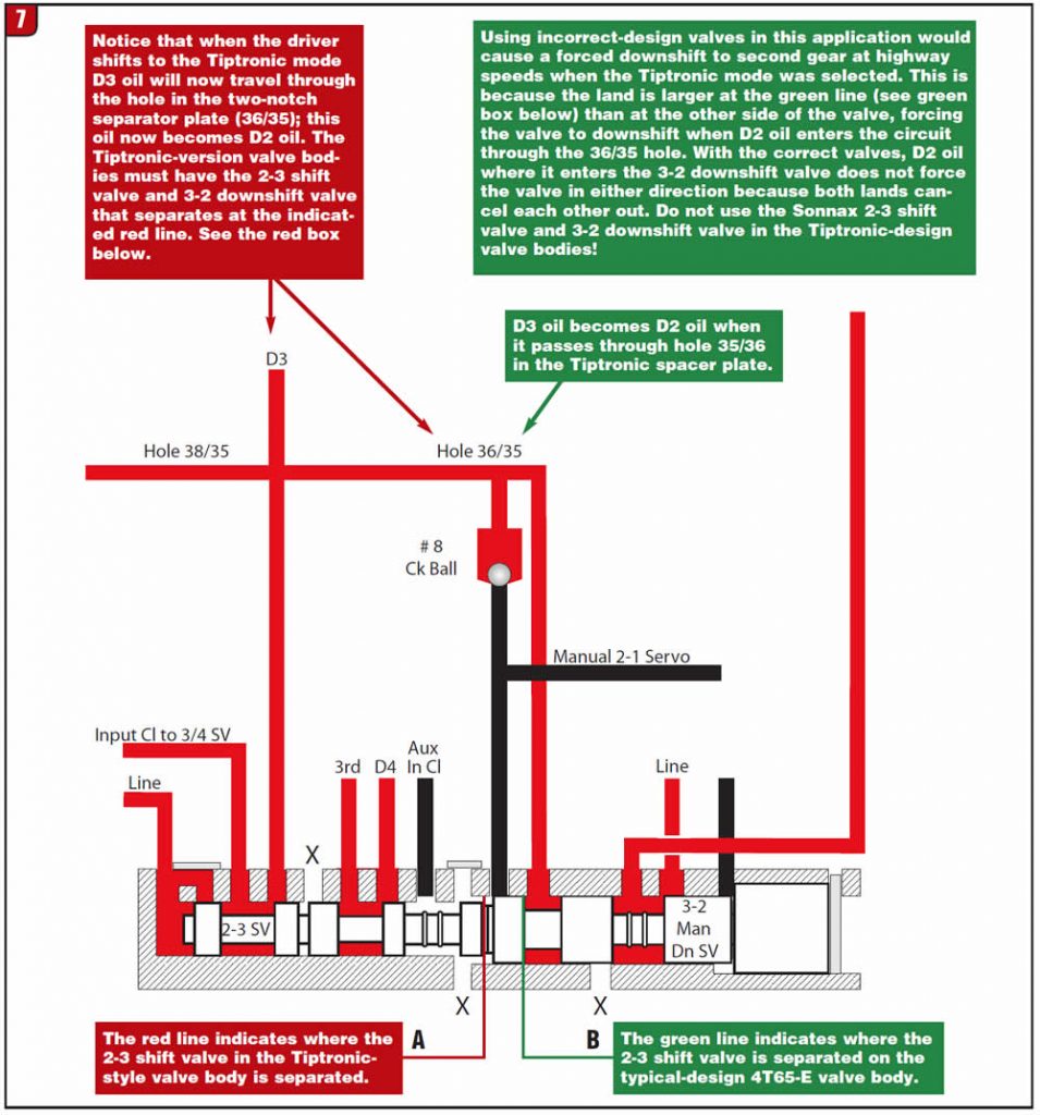
- A) The red line is where the 4T65-E Tiptronic 2-3 shift valve is separated.
- B) The green line is where the typical 4T65-E 2-3 shift valve is separated.
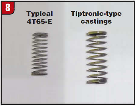
So the next time you’re working on one of these units, I hope this article will help you in identifying the 4T65-E “twins.” There is one more thing to look out for, and that is the torque-signal regulator spring; however, the springs are far from twins (Figure 8).
Thanks to Gary Barati from Mr. Transmission in Burlington, Ontario, for assisting me in this research.

Carlos Costa is the owner of Valve Body Builders, a valve-body remanufacturer with headquarters in Cambridge, Ontario.


