TASC Force Tips
- Author: Bob Warnke
- Subject Matter: Hydraulics
- Issue: Understanding converter clutch controls
Hydraulics Fundamentals
An understanding of hydraulics is essential for properly diagnosing and repairing transmission problems. This is part two of a two-part article on how an understanding of converter clutch control aids in transmission diagnostics. Part one described fluid path and torque converter terminology. Part two examines the source and factors affecting the control of the clutch.
Oil Path Review
Flow is required in a two-path converter to hold the clutch piston away from the cover. Flow is required in both two- and three-paths to charge the converter and dissipate heat. Pressure is required in both to apply the clutch. So, you ask, what’s the difference, then, between a two- and three-path?
It’s All About the Clutch
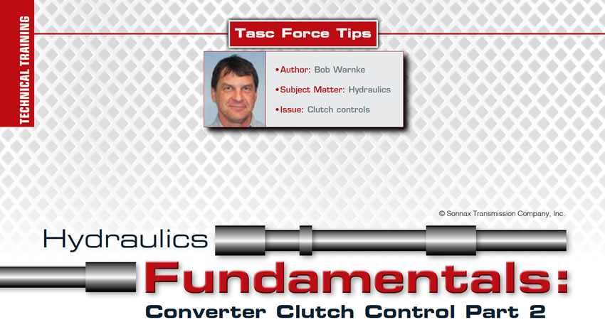
A two-path utilizes release and apply oil to control the position of the lockup piston. When a two-path clutch piston contacts the cover, flow is minimal across the friction surface (Figure 1).
Figure 1 – Two-Path 6L90 Converter
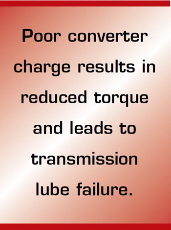
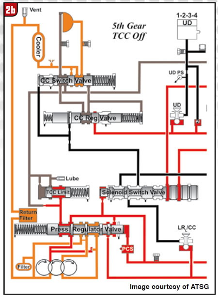
The transition from the release oil holding the piston off the cover, to apply pressure loading the piston onto the cover, is the function of the clutch control/switch valve (figures 2A and 2B).
Figure 2A – 68RFE Clutch Control (TCC Off)
Figure 2B – 68RFE Clutch Control (TCC On)
In some instances, a piston orifice or grooved friction allows a small amount of apply pressure to wash over and cool the clutch lining. This wash is a pressure drop, compensated by the TC regulator valve (Figure 3).
Figure 3 – 6L90 Oil (TCC On)
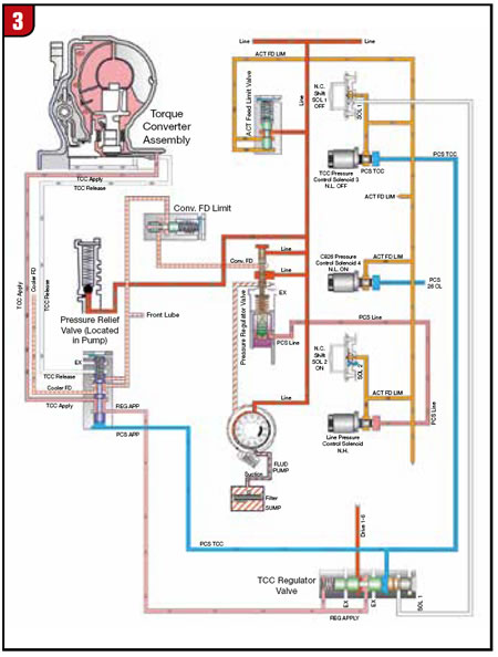
As torque increases and the TCM recognizes slip, the TC solenoid and TC regulator combine to control the slip speed. Slip speed or rate is the difference between engine RPM and turbine RPM.

A three-path has a separate clutch apply path (Figure 4).
Figure 4 – Three-Path ZF8 Cover-Fixed Clutch
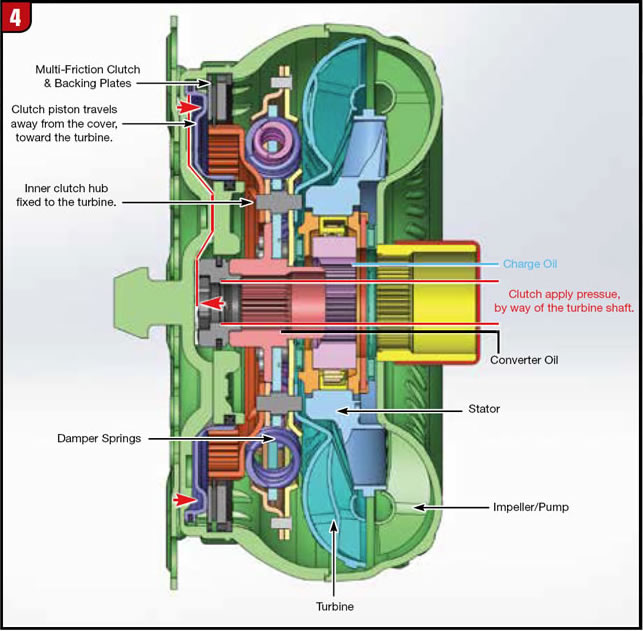
Charge pressure and flow is uninterrupted during clutch apply on a three-path. Because of this flow, a three-path clutch can be applied under high torque or low speed. (The two-path can develop a shudder or friction failure when subject to those conditions.)
Charge & Release Pressure
A converter will not charge properly if the pump output is low. Atmospheric pressure (Pa.) reacts on fluid, forcing it through the filter into the pump inlet. Upon rotation, the pump has a lower inlet pressure than Pa., so fluid is drawn in. If the case vent is plugged, the filter restrictive or fluid viscosity is high, flow into the pump will be low. If a surface is warped, air is pulled in easier than fluid and aerated fluid or cavitation occurs. No Pa. at pump inlet causes low pump charge, noise and low converter charge.
Isolating main regulator valve resonance from pump cavitation can be difficult. Some suggestions are to overfill, increase venting or pressurize the sump. Poor converter charge results in reduced torque and leads to transmission lube failure. A flow meter can isolate, then prove the fact and the fix. Poor charge is obvious, as the vehicle will not move until the converter is purged of air. The lack of lube until charged is not obvious.
Two-Path, Clutch Release
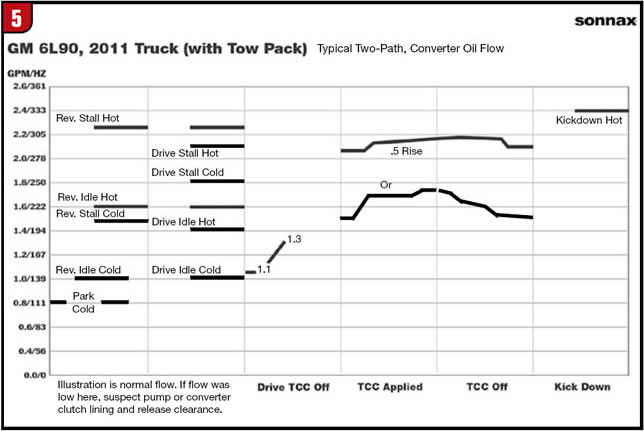
Insufficient release allows the clutch to drag, which relates to rough idle and eventually friction overheat. Clutch release clearance is a dimension accounted for during the assembly of the converter. Poor clutch release can be identified with a scan tool as a surging turbine RPM or by flow, using a SonnaFlow® Cooler Flow Test (Figure 5). The best position to check release oil, or the cause of a dragging clutch, is in reverse, during a hot idle.
Figure 5 – 6L90 SonnaFlow®
Two-Path Apply Pressure
In review, we noted apply pressure is a variable, controlled by amperage to the TC solenoid, which solenoid output moves the TC control and then the regulated apply valve. That’s a long sentence for a long sequence of events. The majority of two-path lockup circuits have the TC control stroke first to switch the oil path. Once the release path is exhausted, the apply path gradually loads the piston onto the cover (Figure 2). The TC control valve has a much lower spring rate and larger reaction area to ensure it remains stroked. Note the word “ensure” — what if the control valve does not stroke all the way? In some instances, the converter paths in and out are restricted by a partially stroked valve, resulting in a super-heated converter. The second reaction from the TC solenoid output is the position of the TC regulator valve. The regulator valve is continually moving, in connection with TCM slip control. That activity equates to bore wear. Bore wear might be addressed by installing a stronger regulator spring or blocking the apply valve into high apply pressure. This also results in a sequence of events:
- The converter will not release properly for up/down shifts, so they are harsh.
- The clutch lining starts to flake due to stress, damper springs break, and the piston is deformed because of over-pressure.
- The lining goes to the radiator and the converter goes to the rebuilder, neither is happy.
We need to remember, line pressure feeds the converter regulator valve. By design, most valves limit apply pressure to the TC piston around 130 psi. If the apply pressure is modified and line pressure is elevated as well (by wear or modification) the clutch piston can receive 150-200+, pressure across the area.
Three-Path Control
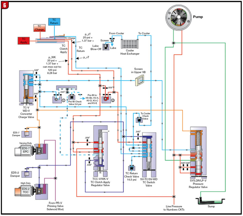
The charge pressure of a ZF8HP is illustrated in Figure 6. PzT will decrease as the clutch applies, but PzT is not eliminated. Release pressure in the two-path is eliminated. Monitoring PzT will indicate if converter feed is sufficient and the TC valves have stroked. PzT is not checking the clutch apply circuit. Clutch apply maintains about four psi of pre-fill in this ZF8HP.
Note: A problem can arise in any three-path converter if charge pressure leaks into the isolated apply circuit. The extra pressure in the clutch housing is amplified by centrifugal force and crowds the clutch. The leak into apply can overwhelm an exhaust slot or relief in the valve body. Most three-paths do not have an apply tap, but we can check the circuit with an air test of the apply circuit in the case. On the bench we can use a turbine shaft. Fluid and air should not continue to leak into the charge or converter out circuit (Figure 6).
Figure 6 – ZF8 TC Apply
Issues Common to Both Designs
Head Pressure
A restriction in the flow within the converter, (turbine or clutch) or radiator can affect the valve action (Figure 7).
Figure 7 – Valve Ratio
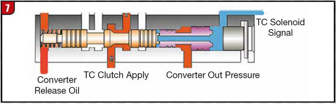
Some valves have a circuit connected to either apply or to charge that cause the valve to stroke in relation to converter pressure, which improves balance and control. If the clutch lining was changed to a non-grooved type, or turbine washers changed or the radiator plugged from a previous failure, the TC apply can be very slow and a shudder or slip arise. In this instance, bypass the radiator and re-drive or install a flow meter and compare to a functional unit.
Solenoid Control
A common problem relative to many drivability issues is excess or low solenoid flow and pressure. We discussed the importance of a TC apply regulator valve. A solenoid regulator valve is equally important (Figure 8).
Figure 8 – Solenoid Leakage
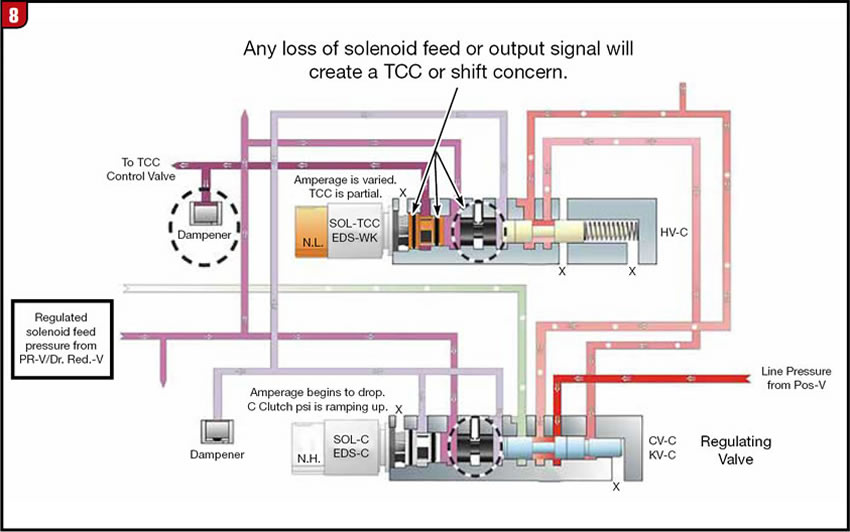
Too much pressure in causes too much pressure out, in this case premature lockup and slow release. Low pressure causes TCC shudder and slip.
Ensure you vacuum test all these regulator valves mentioned that affect converter feed and apply:
- Main Regulator
- Solenoid Regulator
- Converter Regulator
The main point to remember is in reference to the clutch. The two-path requires a good clutch friction to separate release and apply pressure. The three-path relies on seals and/or bushings to control the clutch apply. From the driver’s seat, we are not aware of the design, but a shudder or lack of lube is approached differently once we open them up for repairs.


