Taking the Guesswork Out of Parting - Transmission Digest

Taking the Guesswork Out of Parting

Note: This article, the second in a two-part series on proper parting procedures, takes a look at a better method.

Taking the Guesswork Out of Parting 

Torque Converter Tech

Author: Ed Lee

Torque Converter Tech Tips

  • Author: Ed Lee

Note: This article, the second in a two-part series on proper parting procedures, takes a look at a better method.

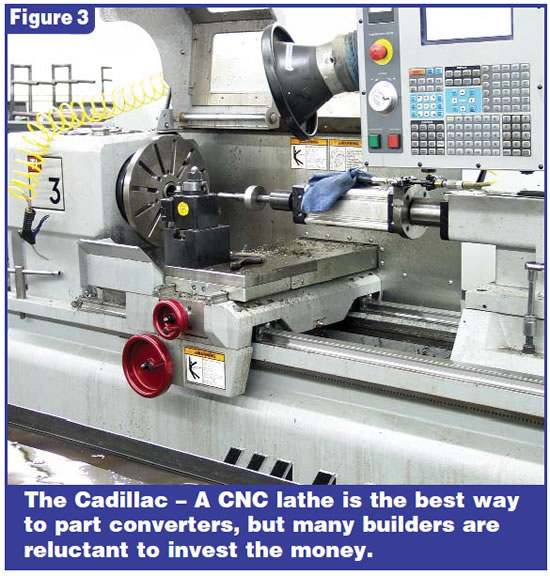
When you’re parting a torque converter, a CNC lathe is the Cadillac of parting devices. With a CNC lathe, you can cut 50 or more converters apart in an hour and virtually eliminate the follow-up machine work – bowl build-ups, installation of renewal rings and general cleanup – that is necessary with any other conventional method for parting the same converters.

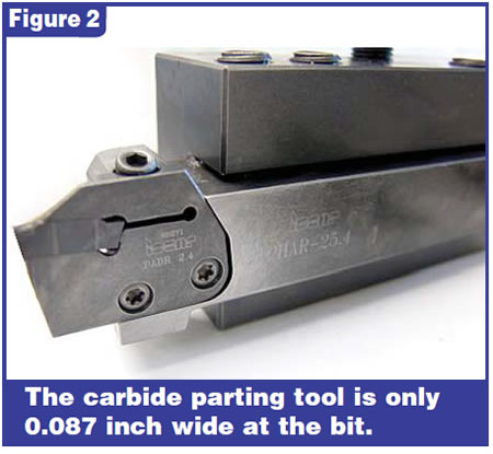
One of the factors that allows extra machine work to be eliminated is the small amount of material that is removed when the converter is cut. The bit of the parting tool on a CNC lathe is a 0.087-inch-wide carbide parting bit held by a boring bar.

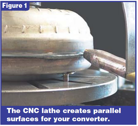
This bit removes a band of material only 0.087 inch wide and leaves two perfectly parallel surfaces. Working with parallel surfaces makes it easier to reassemble the converter and ensures that the halves run true. The life span of the cutting bit is remarkable, considering its narrow width. Operators are cutting 400 to 500 converters with a single side of an insert. They claim they break more bits setting up programs than they do cutting converters.

Two factors keep shops from parting their converters on a CNC lathe: fear of the unknown and the startup cost.

The fear factor comes from a general reluctance to join the computer world and is multiplied by the fear of a computer-run piece of machinery. This fear doesn’t have much foundation. The startup program on a CNC lathe can be set up in less than an hour, and once it is set up additional converters can be added to the program in less than 15 minutes. For each new converter, only the dimensions for the diameter and depth of the cut need to be changed.

As for the startup cost, a CNC lathe will cost more than most older shop owners paid for their first homes. Luckily, the machinery will pay for itself within six months to a year. The CNC lathe will continue to pay back, not only in increased production but also in reduced tool costs and labor savings. Removing the human factor from the parting procedure is where the labor savings is most noticeable.

The run-cycle time on a CNC lathe starts when the operator presses the start button and ends when the cut has been completed and the tool has returned to the at-rest position. Run-cycle times usually average 19 to 30 seconds but do go as high as 45 to 50 seconds on large-diameter converters like Allisons and 4L80-Es.

Parting converters on a CNC lathe isn’t for everyone. However, if you would like to cut your converters more quickly, be more precise in your cutting or would just like parallel surfaces to work with, you may want to consider looking into this method.

Special thanks to Mark Mustard of Branting Industries for his technical assistance in writing this article.

Ed Lee is a Sonnax technical specialist with a focus on issues of interest to torque-converter builders. ©Sonnax 2005

You May Also Like

Sherlock Holmes Approach to an AB60 No-Move Situation

The effectiveness in diagnosing automatic transmission malfunctions is an art form. Although there are similarities among the wide varieties of transmissions on the road, each transmission has its own peculiarities. Aside from having mechanical, hydraulic, and electrical hardware systems to contend with, software/programming issues and various vehicle platforms make diagnostics much more difficult.  Using scopes provides

ab60

The effectiveness in diagnosing automatic transmission malfunctions is an art form. Although there are similarities among the wide varieties of transmissions on the road, each transmission has its own peculiarities. Aside from having mechanical, hydraulic, and electrical hardware systems to contend with, software/programming issues and various vehicle platforms make diagnostics much more difficult. 

GM 6T40 Pump Identification Guide

The 6T40 was introduced in 2008 for General Motors front-wheel-drive cars in the Chevrolet Malibu and has gone through several changes throughout its three generations, specifically in the pump area. The 6T40 is closely related to the more lightweight 6T30 and the heavier duty 6T45 and 6T50. Generation one started phasing out during the 2012

Seeing the Forest AND the Trees

They say that the proverbial phrase “I couldn’t see the forest for the trees” means that a person or organization cannot see the big picture because it focuses too much on the details. Related Articles – 4L60E Harsh 1-2 Shift – TASC Force Tips: Diagnosing 8L45 & 8L90 Shift Complaints – TASC Force Tips: Hydraulics

The Manifold Pipeway

The Honda six-speed transmission has been on the bench of many specialty shops for one reason or another (figure 1). But, for those of you who have yet to lay your hands on one, mounted on the upper side of the unit is one of the largest, if not the largest solenoid and pressure switch

8L90 Vacuum Testing

Below are the diagrams for vacuum testing GM 8L90 transmissions. Note: OE valves are shown in rest position and should be tested in rest position unless otherwise indicated. Test locations are pointed to with an arrow. Springs are not shown for visual clarity. A low vacuum reading indicates wear. For specific vacuum test information, refer

Other Posts

Critical Wear Areas & Vacuum Test Locations for FORD 6R80/6R100

Note: OE valves are shown in rest position and should be tested in rest position unless otherwise indicated. Test locations are noted with an arrow. Springs are not shown for visual clarity. Low vacuum reading indicates wear. For specific vacuum test information, visit www.sonnax.com. Related Articles – Hydraulics Fundamentals: Shift & Relay Valves – Another

Hydraulics Fundamentals: Shift & Relay Valves

Shift valves and relay valves share a lot of the same duties. This article is one of a series by Sonnax exploring how valves and hydraulic circuits work and what results when they quit functioning correctly.

Another 62TE ‘No-Move’ Possibility

Most seasoned techs have several quick diagnostic steps they take when faced with a transmission malfunction. The type of problem and transmission determines which steps to take. For example, a “no-move” condition. Related Articles – Ford 8F35 maintenance tips: Planetary failure and no-pressure conditions – Don’t fear customer complaints about CVTs – Shift Pointers: A Chrysler

Hydraulics Fundamentals: Clutch Regulator Valves

Knowing how these circuits work and the slightly different variations that the manufacturers utilize should pinpoint any valve body-related issues