TC Tech Tips
- Subject: Rebuilding the new GM captive clutch
- Essential Reading: Rebuilder
- Author: Ed Lee
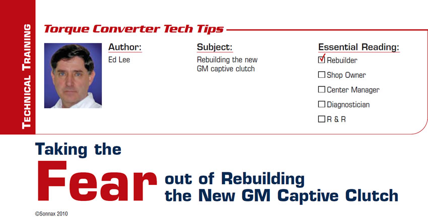
The new General Motors captive clutch has four spring-steel straps that restrict the rotational movement of the piston. One end of each strap is riveted to the piston and the other end is riveted to the cover (figures 1a and 1b).
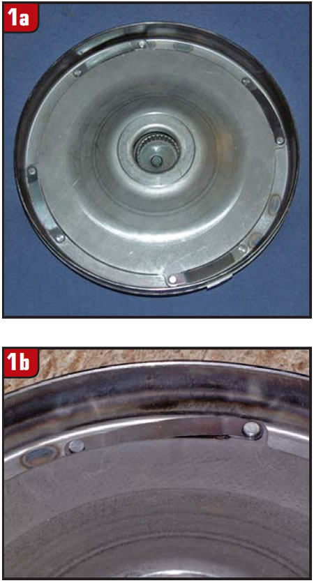
There’s a rebuilding fear factor in this setup because the rivet at the cover end of the strap passes through the cover and is very susceptible to leaking if disturbed (Figure 2).
One way to lessen the chances of a leak in this area is to avoid disturbing this rivet during the rebuild process. It is possible to rebuild the lockup clutch for this converter by removing only the rivets at the piston end of the straps.
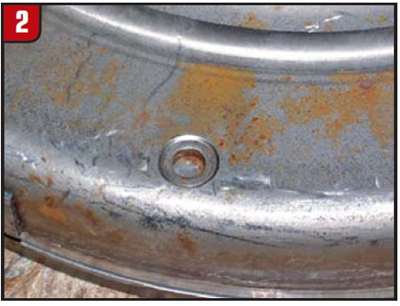
The same tools rebuilders use to prep the edges of the impellers and covers prior to the weld process can be used to remove the rivets. The major portion of the rivet head can be removed by a hand grinder with the 41/2-inch abrasive wheel. The final portion of material can be removed with the angle air grinder with a 2-inch abrasive disk (Figure 3).
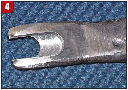
Once the rivet head has been removed and the piston is properly supported, the remaining part of the rivet can easily be driven out with a punch. A tool for supporting the piston can be made from a 6-inch-long piece of steel flat stock 0.120 inch thick by 1/2 inch wide. Machine a slot in the end of the flat stock the width of the rivet head (0.250 inch).
Continuing the slot an additional 0.250 inch, the 0.060- to 0.065-inch depth of the rivet head will allow you to use the same tool to install the replacement rivet (Figure 4).
You will need to narrow and radius the sides of the tool so it will fit between the cover ID and the piston OD while they are in the assembled position (figures 5a, b and c).
Sketch or scribe the inside and outside radii onto the tool to establish a profile for cutting or grinding.
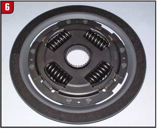
After all four rivets have been removed, rotate the piston 1/4 inch clockwise and lift it out of the cover. The clutch will look like a typical 245mm clutch but will have woven-carbon friction material on both sides (Figure 6).
Measure the thickness of the OE piston, because as with other captive clutches there is limited TCC-piston travel.
Another unique feature of the GM captive clutch is the way the clutch-release clearance is set. Since the turbine hub does not contact the cover, the converter endplay is the clutch-release clearance. If you followed the same procedure as with any new converter and checked the overall height and endplay before the converter was cut apart, you would know that the clutch-release clearance was about 0.010 inch.
Rebuilding the New GM captive- clutch converter – no worries!

Ed Lee is a Sonnax Technical Specialist who writes on issues of interest to torque-converter rebuilders. Sonnax supports the Torque Converter Rebuilders Association. Learn more about the group at www.tcraonline.com.
©Sonnax2010


