Technically Speaking
- Author: Wayne Colonna, Technical Editor
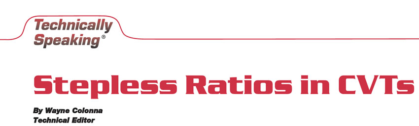
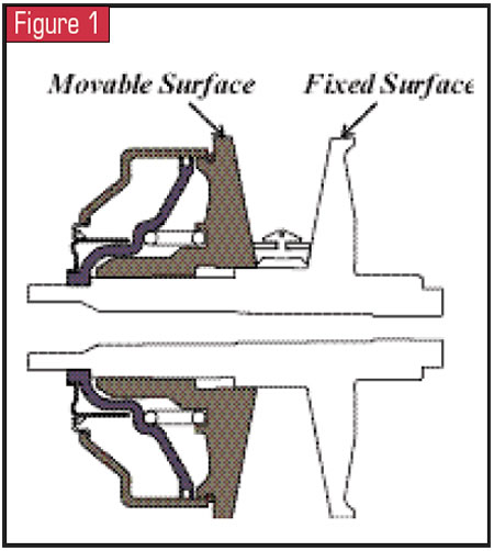
Continuously variable transaxles use pulleys and a drive belt as the components needed to provide the vehicle with stepless gear ratios. The basic construction of a pulley is movable and stationary surfaces (see Figure 1). The drive belt Honda uses, constructed of about 280 elements held together by two 12-layer steel loops, is manufactured by Van Doorne Transmissie (VDT) of the Netherlands, with Honda giving it a little tweaking of its own (see Figure 2).
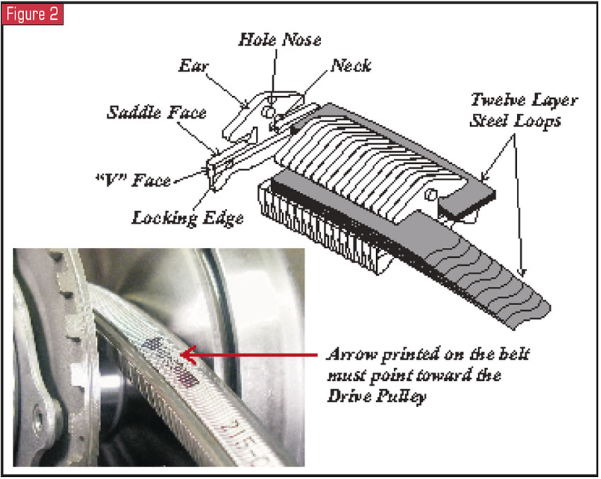
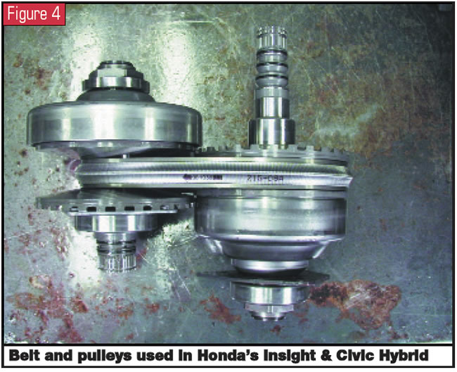
When comparing a belt and pulley set used in a Honda Civic HX (see Figure 3) with those of an Insight and a Civic Hybrid (see Figure 4), the construction appears to be similar in design, yet they have notable differences.
The movable surfaces of the drive and driven pulleys in a Civic HX unit are spring loaded inside the hydraulic control chamber (see Figure 5). The pressure in these chambers resists the wedging action of the belt, and through solenoids and valves (see Figure 6), the pressures in these chambers control the variable ratios. As pressure increases in one of the chambers, the radius of the belt’s riding surface increases. Simultaneously, the pressure in the opposite pulley is decreasing, which decreases the radius of the belt’s riding surface and thereby provides a smooth transition of stepless ratios up or down.
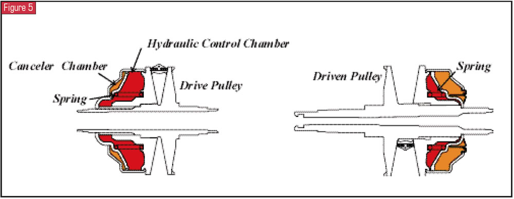
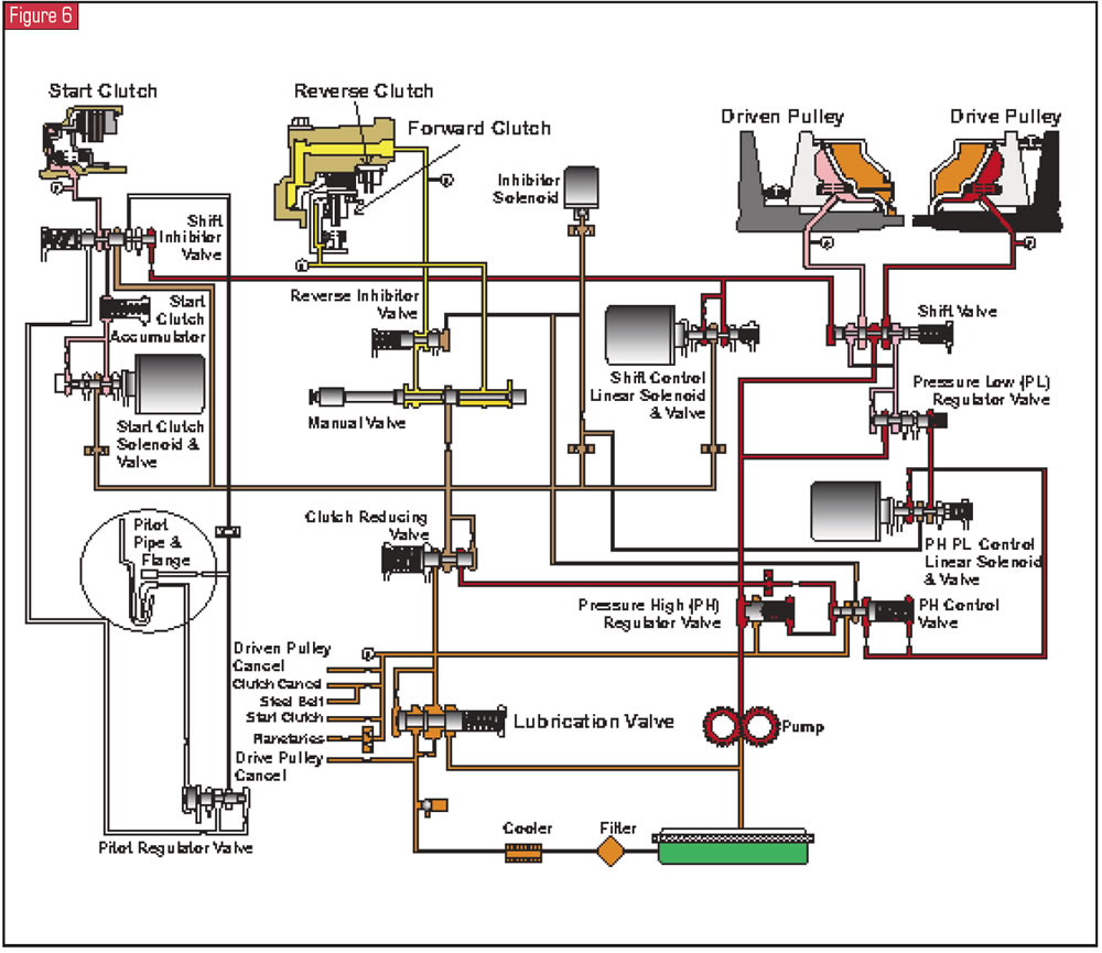
These control chambers are always filled with fluid even when they are not pressurized. As a result, whenever the pulleys are spinning, centrifugal force wants to force this unpressurized fluid onto the face of the movable pulley. To prevent this unwanted force, opposite each of the hydraulic control chambers are canceler chambers filled with lubrication fluid (see Figure 5). This fluid applies enough pressure in the opposite direction that the net force acting on the movable pulley’s face in the pressure chamber becomes zero. In the hydraulic schematic for a Civic HX provided in Figure 6, locate the lubrication valve near the pump. It is from this valve that the drive and driven canceler chambers and other internal components are fed lubrication oil.
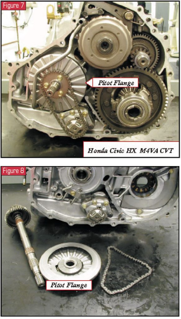
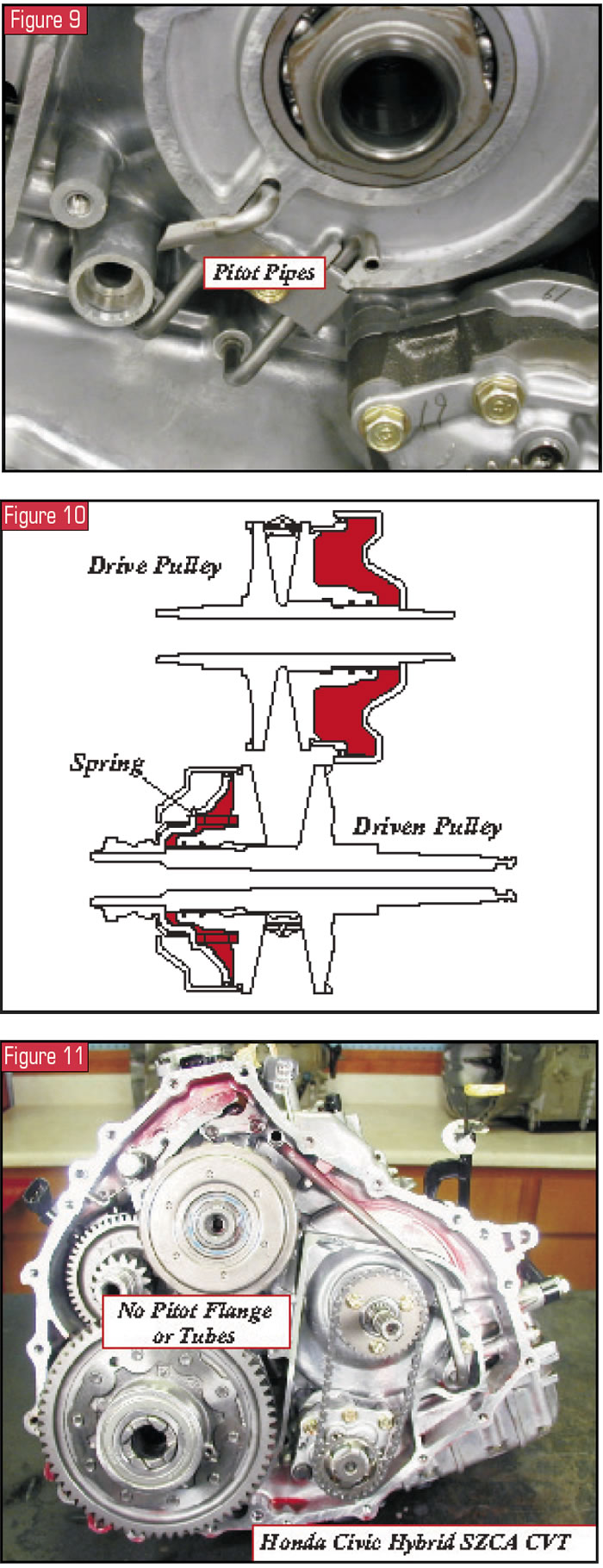
Another aspect of the CVT in a Civic HX is the use of a pitot pipe and pitot regulator valve. This arrangement hydraulically is just to the left of the lubrication valve in Figure 6. The pitot pipe receives fluid slung into it by the pitot flange, which is driven by the input shaft (see figures 7, 8 and 9). This system provides for creep mode and acceleration from a stop in the event of an electrical failure that causes all solenoids to be turned off.
Should this occur, you need to understand several things in order to appreciate the operation of the pitot pipe and pitot regulator valve:
- The shift-control solenoid and valve determine the pulley ratio of the transaxle via the computer. When the solenoid is turned off, the transaxle defaults to a high ratio.
- The pressure high/pressure low (PH/PL) control solenoid is basically an electronic pressure-control solenoid. When it turns off, the transaxle defaults to high line pressure.
- The start-clutch solenoid and valve control the start-clutch apply. When the solenoid turns off, the start clutch is fully released.
- The reverse-inhibitor solenoid inhibits reverse engagement when vehicle speed is above 6 mph. When it turns off, reverse engagement is allowed.
So, if an electrical failure occurs and all the solenoids are turned off, the transaxle is in a high ratio with high line pressure. Reverse engagement is permitted, but without the start clutch, the vehicle will not move. This is where the pitot pipe and regulator valve come into play. Since the pitot flange is splined to the input shaft, as it rotates at engine speed, it slings oil into the pitot pipe. Two pipes actually are involved, as you can see in Figure 9. One pipe moves the regulator valve in proportion to engine speed, and the other pipe supplies pressure to the start clutch through the regulator valve. This pressure to the start clutch also passes through the inhibitor valve, which is stroked by high line pressure via the shift-control solenoid and valve. The result is that the vehicle can move forward in a high ratio and in reverse with the start clutch applying in direct proportion to engine speed.
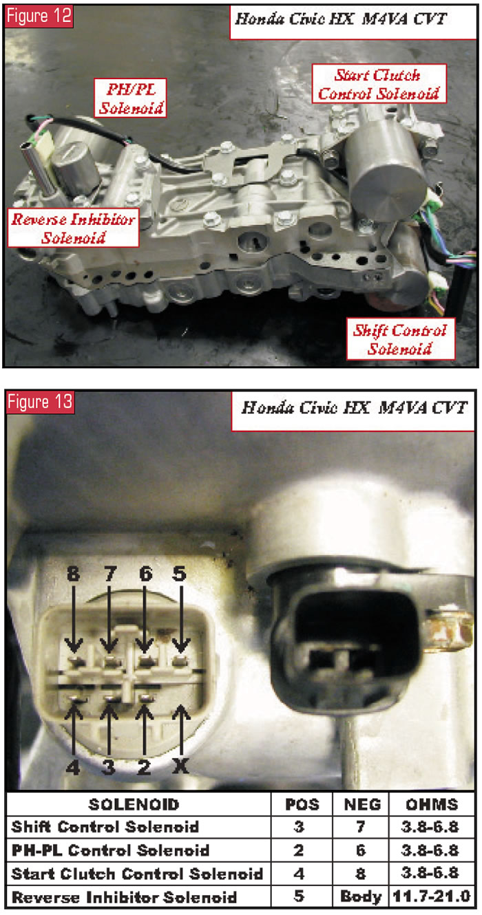
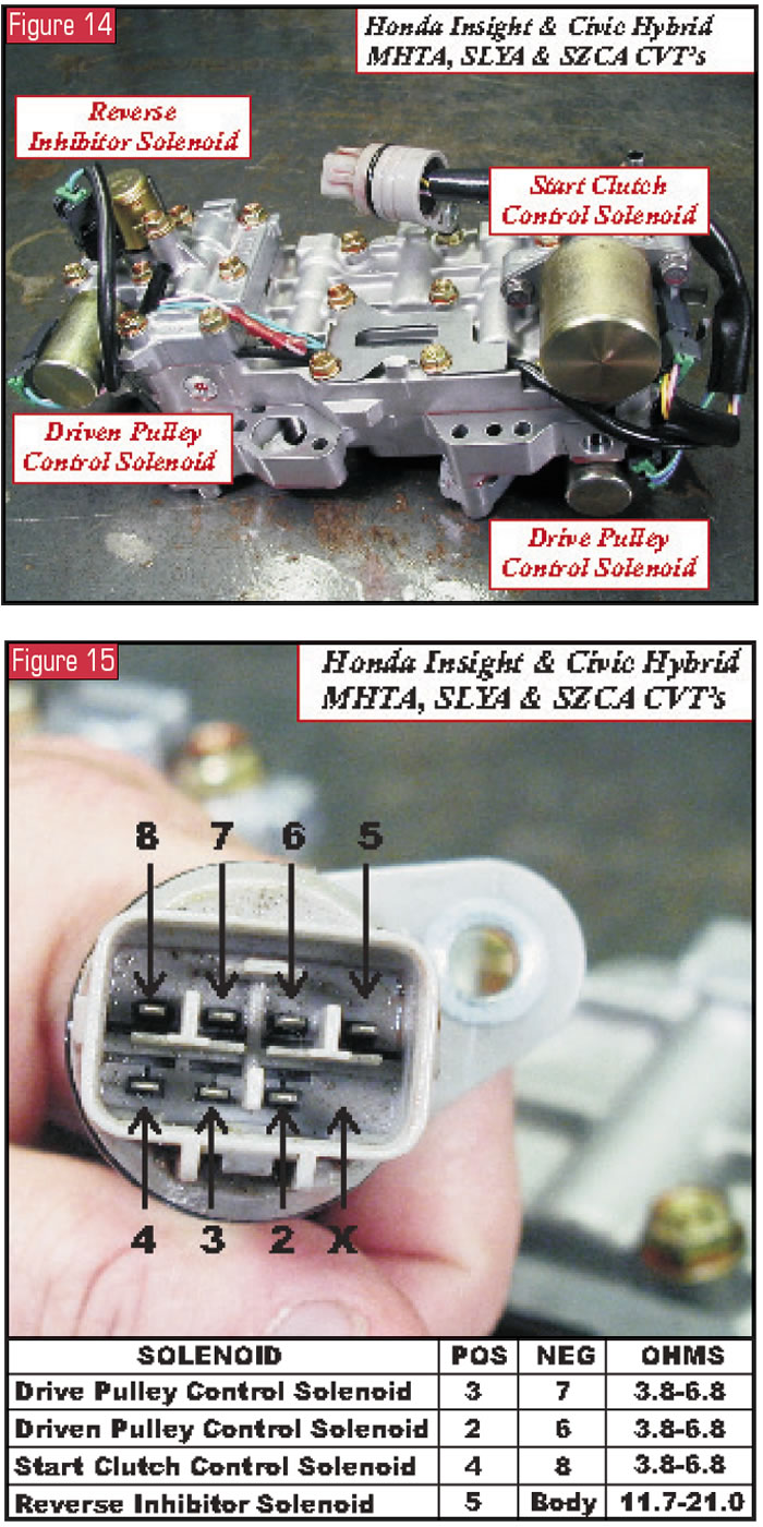
All of this changes when it comes to the CVTs in the Insight and Civic Hybrid. Looking at Figure 10, you will notice two things immediately: The canceler pressure chambers are eliminated and the only pressure chamber with a spring is in the driven pulley. Another difference is the elimination of the pitot pipes and flange assembly, as you can see by looking at the unit in Figure 11 and comparing it with Figure 7. In the event of electrical malfunction with these Hybrid CVTs, the start clutch is applied by a valve simply called the start-clutch back-up valve.
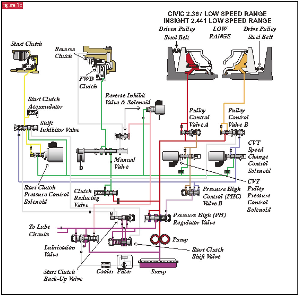
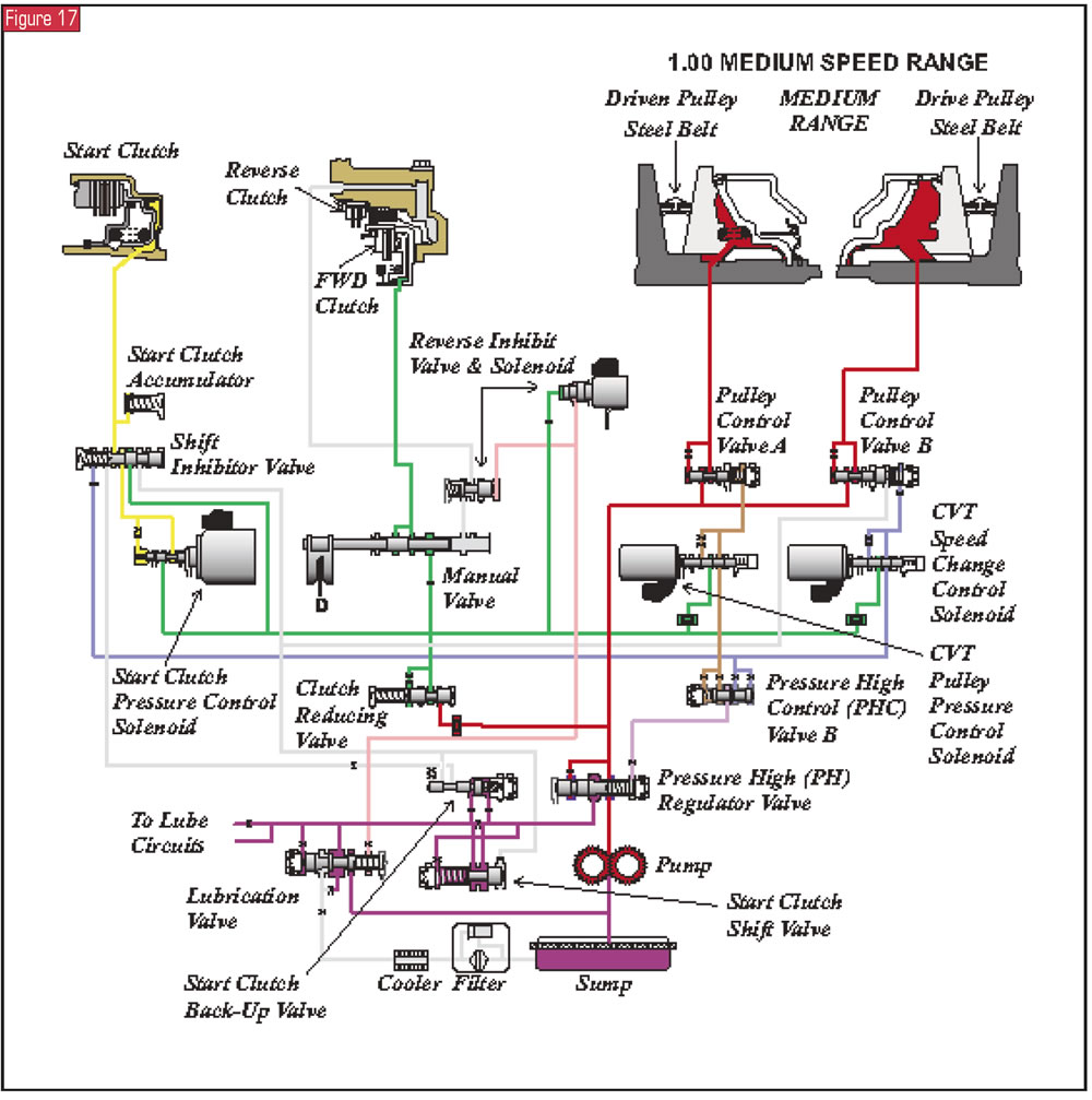
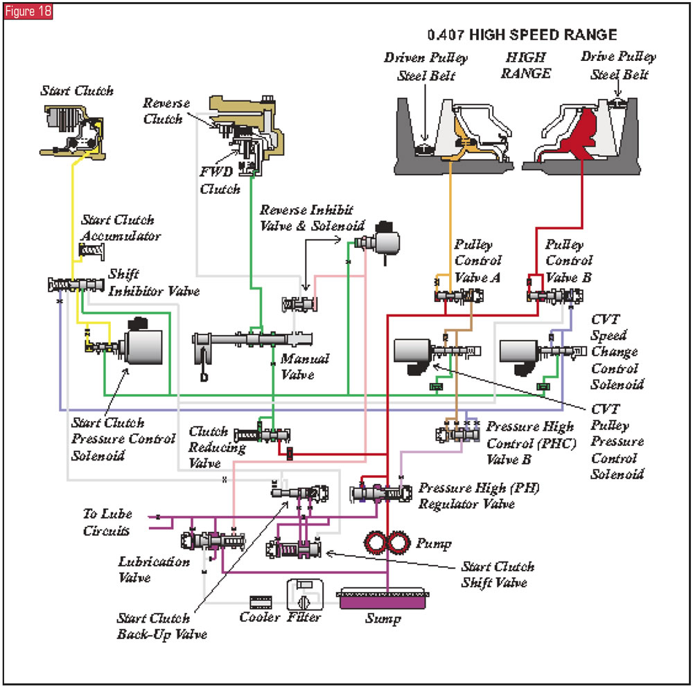
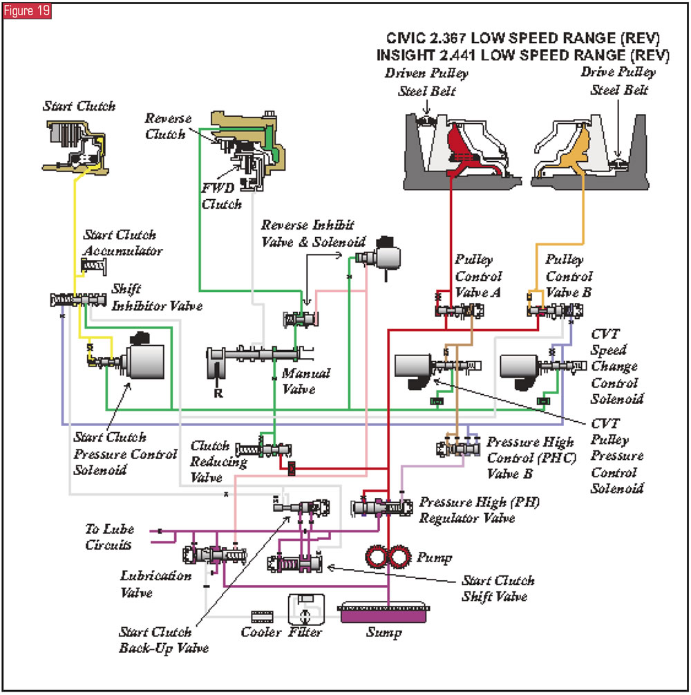
Tying into these changes is the elimination of a shift-control solenoid and the PH/PL-control solenoid. The strategy within Hybrid CVTs is that the pressure chamber of each pulley is controlled by its own solenoid. An interesting observation here is that although the drive- and driven-pulley control solenoids have replaced the shift-control and PH/PL-control solenoids, when you compare the valve bodies and solenoid arrangements between them, you will notice that the solenoid case connectors are the same as well as terminal testing for the resistance of each of the solenoids (see figures 12-15). For a general idea of the hydraulic operation of the Hybrid CVTs, figures 16 through 18 show low-, medium- and high-range operation of the pulleys, and Figure 19 is a hydraulic schematic for reverse.
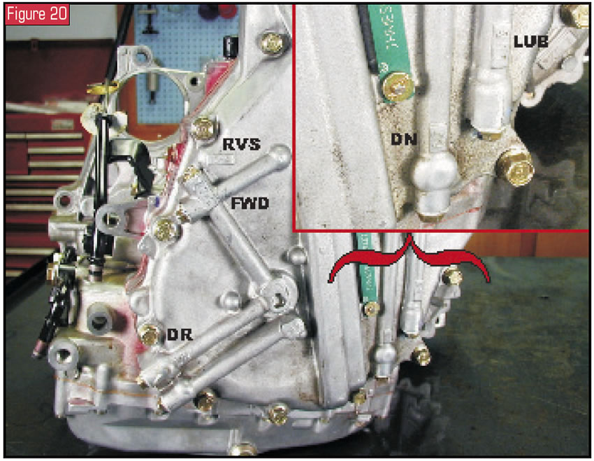
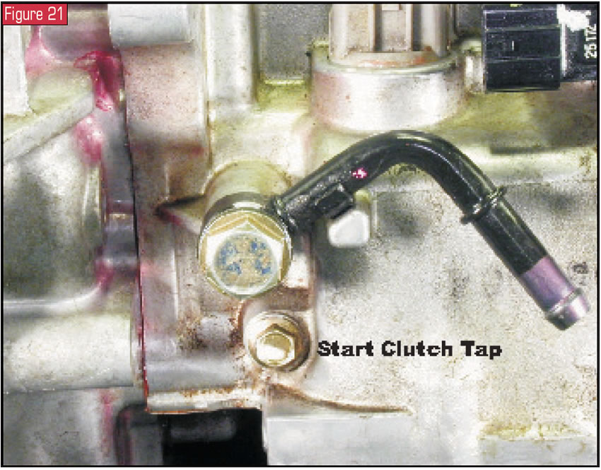
Slipping or no movement due to an incinerated start clutch is probably the most-common failure with these CVTs. At times a pulley will crack or the belt will stretch and produce a similar complaint. Pressure taps for diagnosis are clearly marked on the cases, as you can see in Figure 20. The exception is the start-clutch tap, which is below the cooling line by the pass-through connector on Hybrid CVTs (see Figure 21) and by the dipstick on the Civic HX. Pressures are checked with the wheels off the ground.
For Hybrids, forward- and reverse-clutch pressures at 1,700 rpm run between 228 and 267 psi. The drive pulley will be between 50 and 92 psi, and the driven pulley will be between 92 and 140 psi at the same speed. Lubrication pressure is checked at 3,000 rpm and will be between 36 and 58 psi. The start clutch at idle is usually between 35 and 40 psi, and at stall it will be between 120 and 130 psi.
Civic HX vehicles are checked at 1,500 rpm, and the pressures are 200 to 253 for forward and reverse clutches, 30 to 100 on the drive pulley and 210 to 330 on the driven pulley. Lubrication and start-clutch pressures check the same way as with the Hybrids.
CAUTION: When you’re checking pulley pressure, if the system goes to failsafe, pressures can exceed 500 psi.
So much more can be written about these interesting Hybrid vehicles and continuously variable transmissions. And in the not-so-near future I am sure we will be visiting them again as more manufacturers are producing them. As a brief glance, here are just a few examples:
CVTs
General Motors designed a CVT that is built in an Adam Opel AG plant in Szentgotthard, Hungary, and is being used in the 2003 Saturn Ion and Vue. GM also is thinking that the CVT can be used in several of its high-volume car lines, including the next-generation Chevrolet Cavalier, Pontiac Grand Am and several Opel models. Audi AG added a CVT to the A4 lineup for the 2002 model year, and Ford has a joint venture with ZF Friedrichshafen AG to build CVTs in Batavia, Ohio. Nissan’s Murano is another vehicle with a CVT.
Hybrids
Besides Toyota and Honda, Ford’s hybrid Escape is on the road. GM has plans to produce hybrids with its GMC Sierra and Chevy Silverado pickups. It also has plans for converting the Saturn Vue with a CVT into a hybrid vehicle. DaimlerChrysler is preparing to offer a hybrid Dodge Durango SUV as well.


