A 2009 Ram 4500 was towed to the shop. This truck had the 6.7 turbo diesel equipped with our remanufactured AS68RC transmission. This vehicle was also equipped with a snowplow, salt spreader, performance tuner, and several communication radios. The vehicle ha a multitude of issues with diagnostic trouble codes stored in several different modules. After gathering the trouble codes, a road test was in order. I connected the scan tool and proceeded to drive the truck. Initially the transmission would not shift, and I noticed there was no input speed signal registering in the PID data. This coincided with the P0717 (no signal input speed sensor 1) code pulled. A trouble code P0560 (battery system voltage) was also stored along with a P2121 (accelerator pedal position sensor 1 performance). I quickly looked at the APP sensor and the scanner data PIDs confirmed that it was working at the present time, so I decided to address that issue after I addressed the transmission issues.
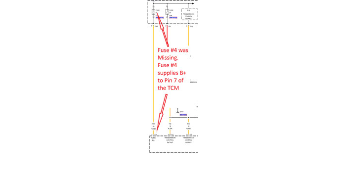
We investigated the P0560 code first. The theory of operation for this code is: “Battery voltage is supplied to the controller and is used to write to the controller EEPROM after vehicle shutdown (similar to Keep Alive Memory).” That seemed like a mouthful. We pulled a wiring diagram and discovered that B+ to the control module comes from the TIPM (Totally Integrated Power Module), fuse #4. Fuse #4 supplies B+ to the TCM (Transmission Control Module) at C2, pin 7. The easiest place to start is checking the fuse since the TCM is under the dash. Once the cover was off and the fuses visible, we saw that fuse #4 was missing. (Figure 1) We were unable to determine why someone had removed the fuse. Kevin replaced the fuse, cleared the codes and then scanned the codes once more. The P0560 was now cleared and did not return. It was time to move on to the next issue…
Now we were going to address the ISS (Input Speed Sensor) code. We still had no speed signal on the scan tool with the engine running. This speed sensor is easily accessible, so we decided to check it while it was still in the transmission. We noticed that the sensor connector was not securely fastened. He inspected the connector and the sensor pins and then secured the plug. This did not fix our issue. We then disconnected the sensor and tested the resistance of the speed sensor itself. The sensor in the transmission tested “OPEN” so we decided to replace the sensor. It was a difficult part to source. They were backordered from the O.E. but we were able to locate one.
The sensor came in a few days later and we installed it. To our dismay, there was still no speed signal on the scan tool. We tested the new sensor and it was good. We were missing something; could there possibly be issues with all of the added aftermarket components? Could the tuner have some effect on the sensor operation?
I had some idea of the direction I would need to go, but I had not worked on this system in the past. It was similar to others, but still different. This vehicle has an AS68RC transmission. This system uses a separate TCM that is located under the dash. This TCM had been replaced prior to coming in to us. All of the B+ and grounds were double checked, and the calibrations correct to the VIN were confirmed. We knew it had been replaced and confirmed that the install was correctly done. I printed out all of the relevant information I could get, including theory of operation, wiring diagrams, and pertinent specifications that were available.
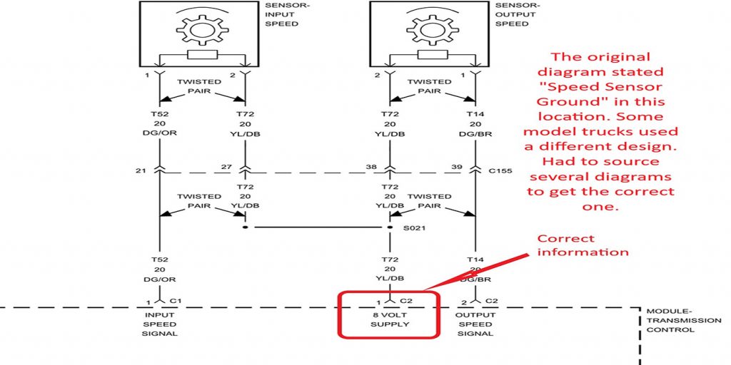
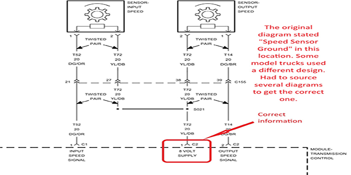
These speed sensors are 8-volt magneto-resistive sensors that generate a square wave signal. It measures the speed of the P1 sun gear which is attached to the input shaft. What was confusing was that the first wiring diagram I looked at, C2 pin 1 at the TCM did not state an 8-volt supply.
In fact, C2 pin 1 was labeled as “speed sensor ground” on this document. That didn’t make any sense. As I looked further and I found a different diagram that was labeled correctly. Now that I had good information and a plan of attack, I started my search for the problem. (Figure 2)
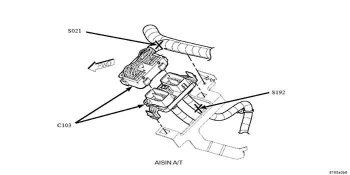
I sensed that I was not having an issue with the 8-volt supply since we were not having any issues with the OSS (Output Speed Sensor), because both sensors get the 8 volts from the same source, C2 pin 1. Regardless, I thought I’d better check it in case there was an issue with the splice S021.
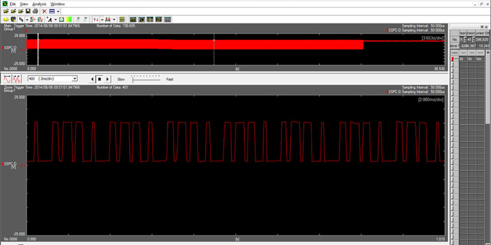
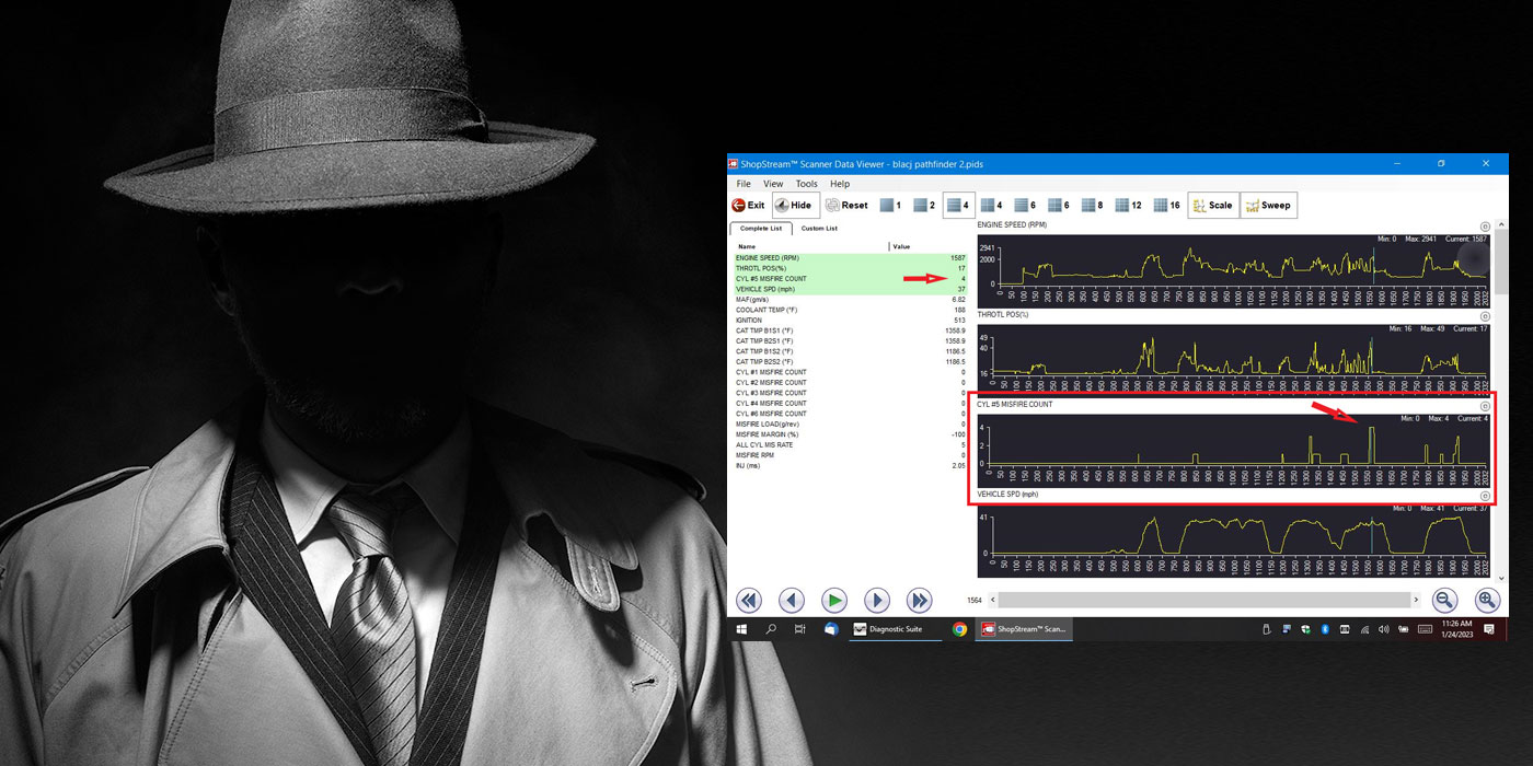
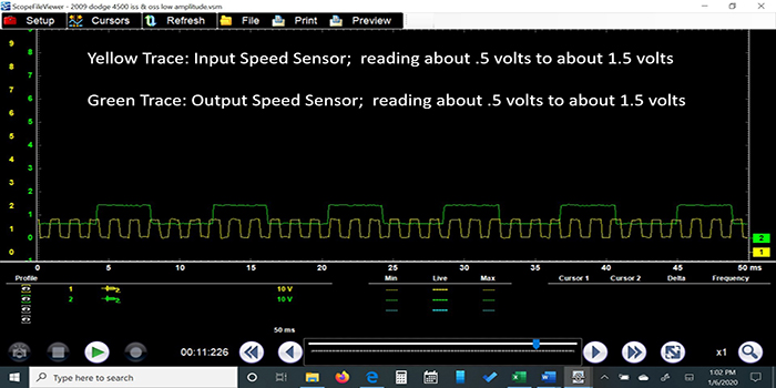
I tested and saw 8 volts at pin 2 of the ISS. I decided to scope the sensor at the speed sensor itself. I was able to get a pattern but there still was no signal shown on the scan tool. The pattern looked odd to me. The amplitude was very low, and I thought there must be something limiting it and perhaps why the TCM couldn’t register a signal. (Figure 3) I would later determine that I was wrong and started to head down the wrong path for a short period of time.
I thought that since the supply voltage was 8 volts, I should at least see 0-8-volt amplitude, or something close to that. In my basic thinking, if you are going to supply 8 volts you should USE 8 volts. Since most of the O.E.M.’s don’t publish their wave form specifications, I was not sure what I was working with or where to find it. So, I went back to double-check all my readings at the TCM. I rechecked all the voltages and grounds. Again, everything checked out. There had to be an issue with the TCM. The original TCM was in the vehicle so I swapped it back in and rechecked. No change in the results.
Racking my brain as to where I would find the crucial waveform information I needed, I looked through the PICO waveform library, and found nothing. I Googled it, and still found nothing. Out of the blue it occurred to me that I hadn’t checked the “Guided Component Test” on the Snap-On scanner. The specs I needed were found there! (Figure 4)
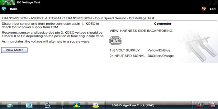
Per this information, the sensor should read .8V to 1.6V. That was precisely what my sensor was generating. Success! Not so fast, though. Why did I not have a PID reading on the scan tool?
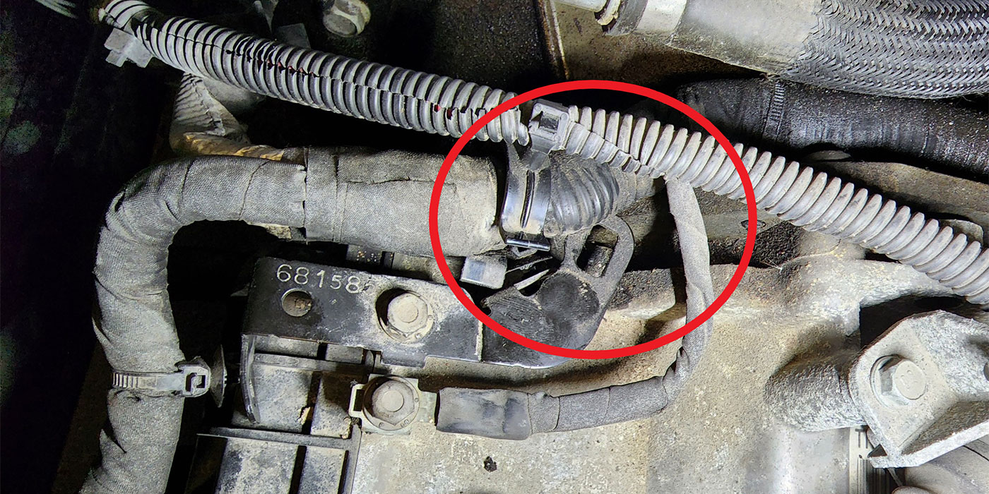
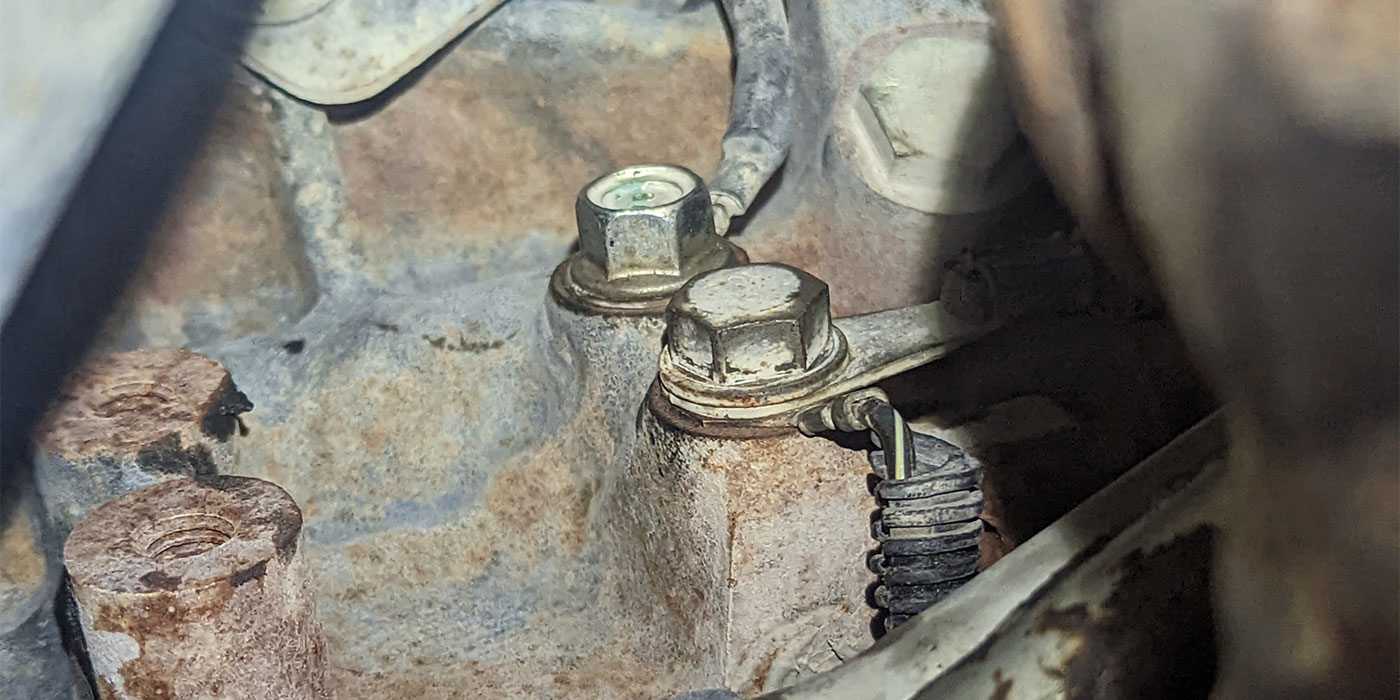
I decided to attach my scope leads to the TCM. I back probed C1 pin 1, and C2 pin 1. With the engine idling there was no pattern shown on my scope. That’s a problem. Now I needed to figure out where the cause was. I knew it wasn’t the 8-Volt supply, because I had 8-volts at both of the speed sensors. I suspected an open circuit in the ISS wires (DG/OG). I started by working my way towards the transmission from the TCM. There is a bulkhead connector just above the master cylinder. (Figure 5)
I checked the TCM side of this connector, and still no signal. It was virtually impossible to back probe the back side, so I took the connector apart and checked the pin fit and made sure I had no damaged pins. I cleaned the connector and reassembled it, making sure the bolt that held the halves together was tight. I started the vehicle again and now had a good pattern and signal on the scan tool.
It seemed to be either a poor connection or the bulkhead connector bolt was not tight enough. It seems that lately connection issues are the source of many a headache. I drove the vehicle and the transmission worked well. I got a good recording of the ISS and OSS patterns for future reference. (Figure 3)
No codes returned. I was happy but something about this was bugging me. When I got back from the road test I hooked up the scan tool, homed in on the ISS PID and watched as I loosened the bulkhead connector bolt. Nothing happened at first, but when I pulled on the connector a slight tug caused the ISS to drop out. We didn’t lose any other data, just the ISS. I tried this a couple times and it was repeatable. I was now satisfied that I’d located the root cause. I tightened the bolt again, cleared the codes, and went for a drive. The ISS fault was gone and the P0560 did not return with the fuse installed.
The APP code, P2121, did not return during this visit, however, it did return a few weeks later and we replaced the APP sensor at that time.
Sometimes you think you’re on the right track only to find out you’re going down the rabbit hole. Some problems are very frustrating while you’re in the moment but, great learning experiences once you conquer them. The key is to retrace your steps, double-check, and think outside the box. Even the most difficult issues can be fixed.
Randy has worked for Certified Transmission for over twenty-five years and is an ASE Certified Master Technician, including L-1. He has been in the automotive industry for over 30 years.