


Before and after overhaul the transmission may experience delayed engagements, coast-down-shift bumps, flared shifts and/or falling out of gear into neutral. Depending upon the severity and consistency of the problem, diagnostic service codes for gear-ratio errors or solenoid performance codes may set as well.

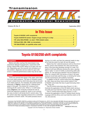
There are several bore plugs in the upper valve body that must retain pressure. The type of complaint experienced is determined by which bore plug has lost its ability to retain pressure. For example, the partial hydraulic schematic in Figure 1 shows the SL1 solenoid energized in first gear.
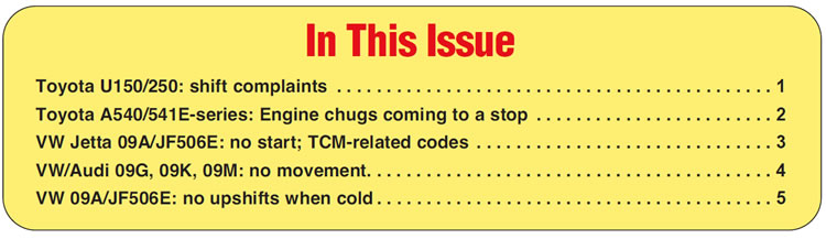
This blocks SL1 pressure from stroking the B1 control valve. When a 1-2 shift takes place (Figure 2), the computer controls the rate at which the solenoid is pulsed off, which in turn controls the rate at which it will stroke the B1 control valve. The B1 control valve then regulates pressure for a controlled application of the B1 clutch. The same process occurs during a 3-4 shift, and then the solenoid needs to stay off to hold the clutch for both 4th and 5th gears.
Notice how SL1 solenoid pressure acts on the end of the B1 control valve between the valve and the bore plug. If this bore plug develops enough of a leak, SL1 signal oil will have difficulty stroking the valve, causing flare or slide 1-2 and 3-4 shifts or preventing shifts altogether. Or, the bore-plug retention may be sufficient to allow for a decent shift, yet during a cruise in 5th gear pressure could leak past the plug, un-stroking the valve, and the transmission will suddenly neutralize.
In addition to the B1 control-valve bore plug (Figure 3, # 62), there are three more control valves in the U150/250 valve body that rely on good bore-plug retention. They are:
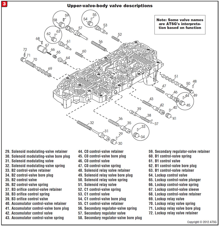
The C0 control-valve bore plug (Figure 3, # 45) –Controls the application of the C0 direct clutch during a 2-3 shift and must hold the clutch on in 3rd, 4th and 5th.
The C1 control-valve bore plug (Figure 3, # 54) -Controls the application of the C1 forward clutch during a garage shift into Drive and must hold the clutch on for 1st, 2nd and 3rd.
The B2 control-valve bore plug (Figure 3, # 34) -Controls the application of the B2 low-reverse brake in manual low for engine braking and must hold the clutch on in 1st.
With the exception of the B2 control-valve bore plug, solenoid performance codes and gear-ratio-error codes may be the result of poor bore-plug pressure retention.
An indication that one or more of these plugs are beginning to leak would be bumpy shifts up and down because of the adapts adjusting for the leak. It is also recommended to inspect the secondary-regulator-valve bore plug, as it is known to crack in the spool area of the plug (Figure 3, # 58).

Replace or modify the leaking bore plugs.

- U150/U250 . . . . . . . . . . . . . . . . . . . Superior K096
- U140/U240 . . . . . . . . . . . . . . . . . . . Superior K097


Before or after overhaul, a Toyota equipped with the A540/541E automatic transmission exhibits a complaint of the engine lugging or chugging when the vehicle is braking and coming to a stop. Additionally one of the brake lamps or reverse backup lamps may not be working.
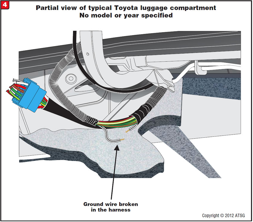
One cause may be a broken brake-lamp and/or reverse backup-lamp ground wire in the harness that is routed through the luggage compartment of the vehicle. The harness that includes the brake- and reverse backup-lamp ground wires runs very close to the deck-lid hinge. Through repeated opening and closing of the deck lid, the wire harness is stretched and/or rubs on the hinge until finally one of the wires in the harness breaks. See Figure 4 for the location of the wire harness in the luggage compartment.
If the ground wire for the brake and/or backup lamps is one of the broken wires, it may cause a PCM-logic issue allowing the TCC solenoid to inadvertently be activated when the brake pedal is depressed, causing the engine to chug or lug as the vehicle is braking to a stop because the torque-converter clutch is applied. As the vehicle is approaching a complete stop and the downshift into first gear is achieved, TCC application is uncoupled because no oil pressure is fed to the TCC solenoid in first gear.
If one of the brake lamps or reverse backup lamps will not illuminate, open the harness and check for broken ground wires. See Figure 5 for a typical wiring diagram that illustrates the wiring ground circuits for the brake and reverse backup lamps.
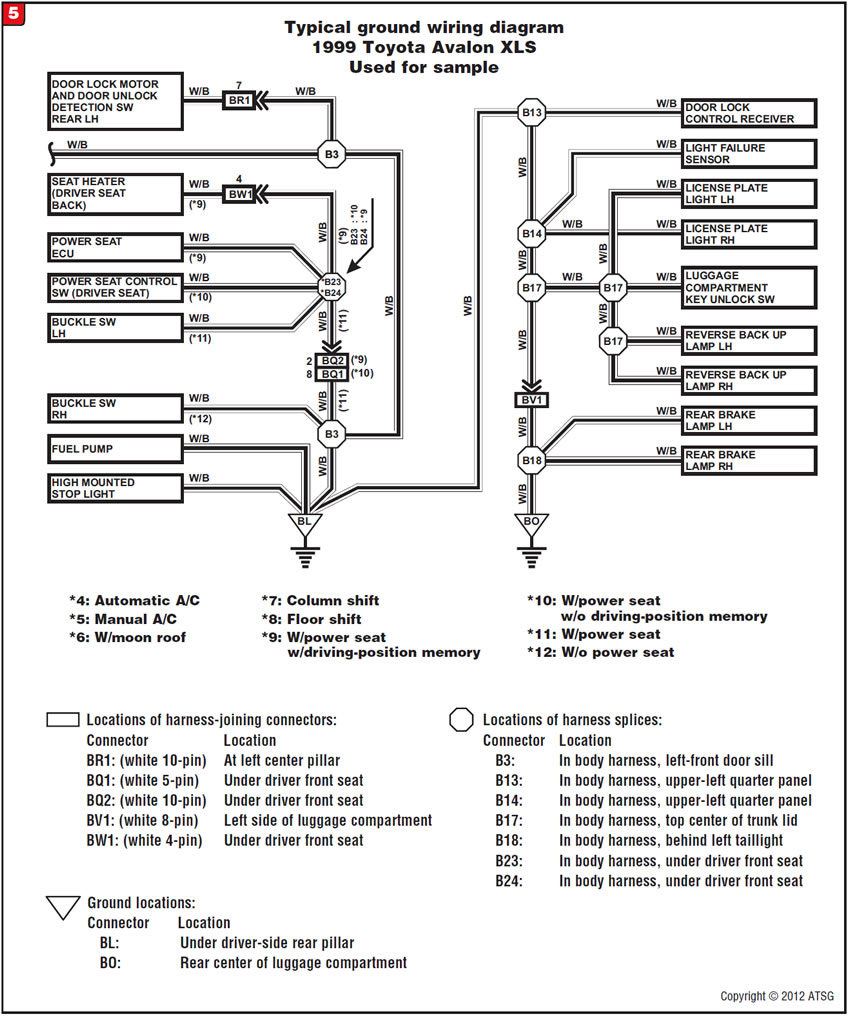
Note: 1999 Toyota Avalon XLS wiring information used for the sample diagram. Since wiring diagrams and information on connectors, splices and grounds may vary from year to year and model to model, consult the appropriate factory manual for the vehicle you are working on.
Repair the harness as necessary, and move or tie the harness away from the deck-lid hinge to reduce possibility of future contact.

After installation of the transmission, the vehicle will not start, and there are TCM codes P0743 for a TCC-solenoid circuit fault, P0753 for a shift solenoid A circuit fault and P0748 for a pressure-control-solenoid circuit fault.
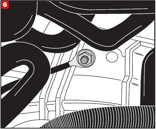
With some Jetta vehicles the No. 2 ground wire runs from the battery to the transmission bellhousing. When left loose or unattached it produces a no-start complaint with TCM-related codes.
Attach the No. 2 ground wire to the transmission bellhousing (Figure 6) and tighten the nut to 11 lb.-ft.(15 Nm).


An 09G, 09K or 09M in a Volkswagen or Audi may experience a no-move condition with the PRNDL lights flashing.
One cause may be that the brake pedal was released before the selector lever was fully engaged into the desired range (Figure 7).
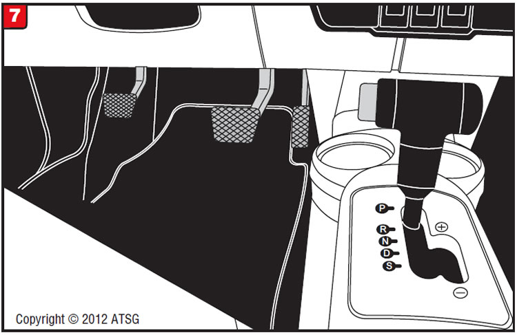
The brake pedal must remain depressed until the selector lever has been placed into the desired range and the transmission has fully engaged. If the brake pedal is released prematurely, activating this safety strategy, depress the brake pedal with the selector in the desired range. The PRNDL lights should stop flashing and the transmission should engage immediately afterward.

Before or after an overhaul, a Volkswagen equipped with the JF506E transmission may exhibit a complaint of no upshifts when cold. The vehicle takes off in first gear and stays in first gear until it warms up for a while.
One cause may be a faulty shift solenoid N92, 2-4 brake solenoid N283 or 2-4 brake timing solenoid N282. The solenoid valves tend to stick or hang up when cold. Figure 8 shows solenoid locations.
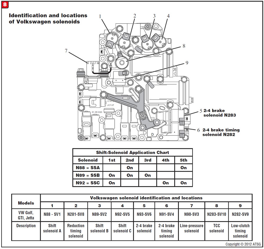
By performing a dynamic bench test of the solenoid, determine the solenoid or solenoids that need to be replaced.
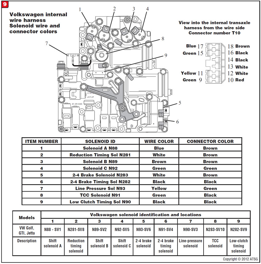
Note: There has been some confusion about the internal wire colors for the Volkswagen version of the JF506E. We have included colors of the internal wires and their positions within the internal-harness connector to assist the technician in assembly and reduce the possibility of cross-connecting wires. Please refer to the diagram in Figure 9 for the internal-harness wire and connector colors.

September 2012 Issue
Volume 29, No. 9
- Toyota U150/250: shift complaints
- Toyota A540/541E-series: Engine chugs coming to a stop
- VW Jetta 09A/JF506E: no start; TCM-related codes
- VW/Audi 09G, 09K, 09M: no movement
- VW 09A/JF506E: no upshifts when cold


