


A 1995 Mitsubishi 3000GT came into the shop in limp mode and with the Sport Lamp in the instrument cluster flashing. The codes that were retrieved were for gear-ratio errors. As it turns out a transmission with an incorrect gear ratio was installed.
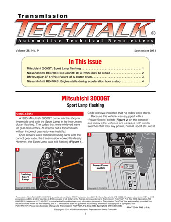
Once repairs were completed using parts with the correct gear ratio, the transmission worked flawlessly. However, the Sport Lamp was still flashing (Figure 1). Code retrieval indicated that no codes were stored.
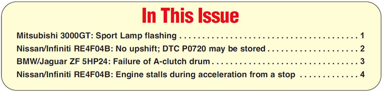
Because this vehicle was equipped with a “Power/Econo” switch (Figure 2) on the console –and many other vehicles are equipped with similar switches that may say power, normal, sport etc. and it is not uncommon for one of these lamps to flash when a transmission-related problem exists – the technician thought this might have something to do with the flashing Sport Lamp.

The technician decided it was time to look at a wiring diagram to see what part the Sport Lamp played in the transmission control system. The wiring diagram revealed no Sport Lamp in the transmission control system.
The technician decided to backtrack and look at a wiring diagram for the instrument cluster (IC), starting from the Sport Lamp and tracing it to where it comes from.
The IC wiring diagram indicated both a Sport Lamp and a Tour Lamp, which is controlled by an electronically controlled suspension (ECS) module.
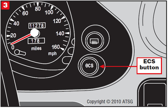
At this time the technician saw a button on the dash marked “ECS” (Figure 3) and decided to scan for trouble codes in the ECS system. Should the scan tool not communicate with this module, you can retrieve the codes manually by using a voltmeter.
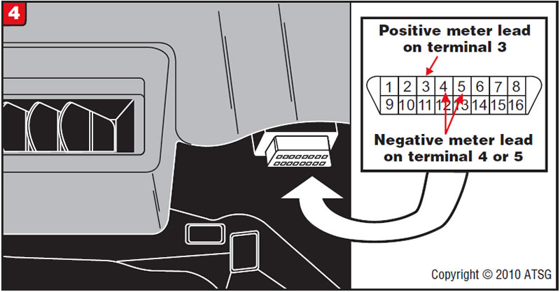
With the ignition on, connect the voltmeter positive lead to DLC terminal 3 and the negative lead to DLC terminal 4 or 5 (Figure 4).
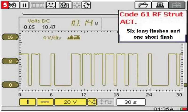
The voltmeter screen shot in Figure 5 indicates six long flashes and one short flash, which would equate to Code 61.
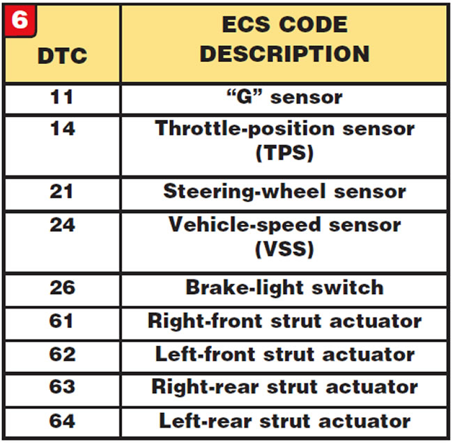
Consulting an ECS trouble-code chart (Figure 6), he found that Code 61 indicates the problem lies in the right-front strut actuator.
When the technician looked at the top of the strut tower, he noticed that there were wires attached to it (Figure 7).
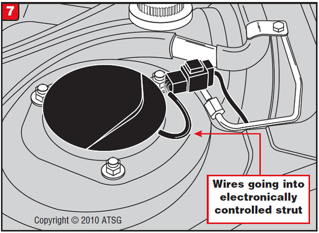
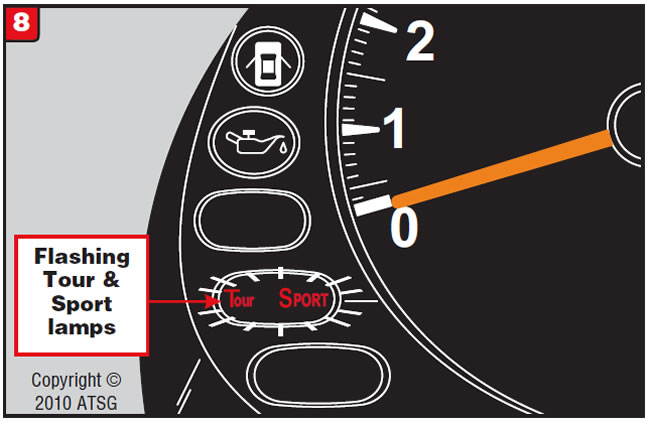
It seems that the ECS module controls the softness or firmness of all four shock absorbers. What further complicated the situation was that the Tour Lamp was burned out. When a problem exists in the ECS system, both the Sport Lamp and the Tour Lamp are supposed to flash (Figure 8).

When the ECS system is working properly, upon startup the Tour Lamp will be illuminated and the ECS module will automatically control the damping of the struts in accordance with driving conditions.
When the ECS button is pushed, the system will switch to “Sport Mode,” the Sport Lamp will illuminate and strut damping is set to the firmest setting at all times regardless of driving conditions.


After an overhaul a Nissan/Infiniti vehicle equipped with the RE4F04B automatic transaxle exhibits a condition of no upshift. Upon checking for codes, you may find DTC P0720 stored.
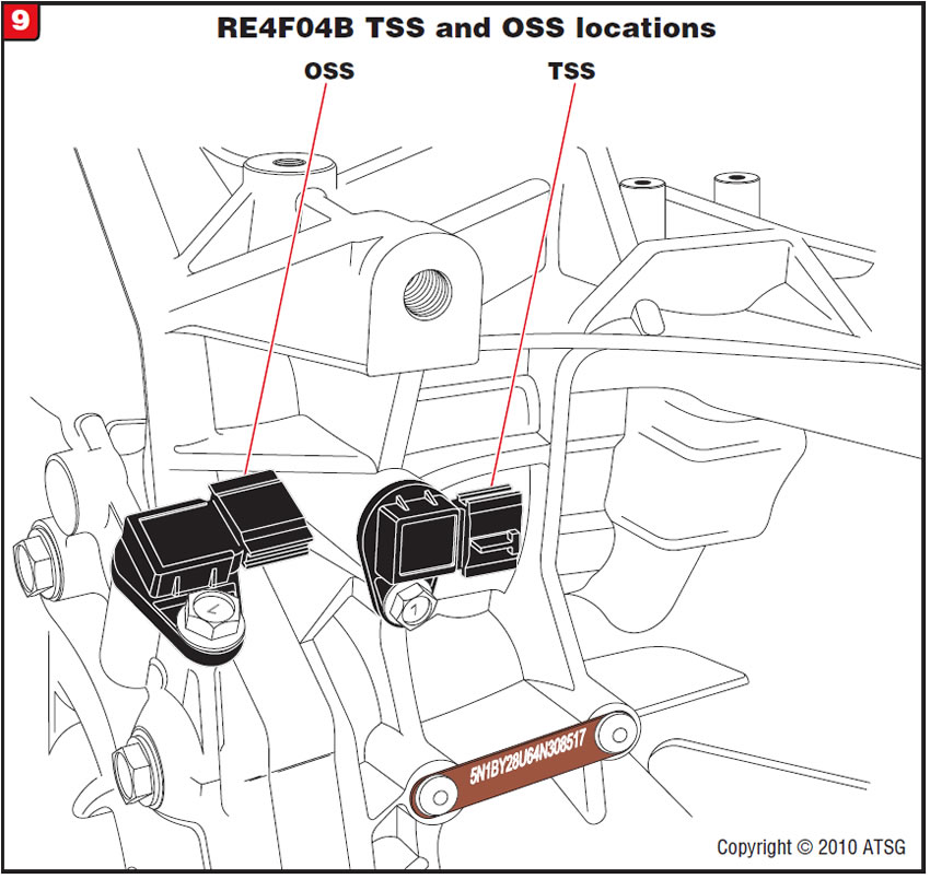
One cause may be that the connectors for the output-speed sensor (OSS) and turbine-speed sensor (TSS) are cross-connected. Some late-model Nissan/Infiniti models with the RE4F04B transmission use both a TSS and an OSS. Both are Hall-effect sensors and are on the back of the transmission near the driver-side axle. Refer to Figure 9 for locations of the two sensors.
If the OSS connector is incorrectly plugged into the TSS, the transmission control module (TCM) will not detect any output speed when the vehicle is taking off, resulting in no upshift and storing DTC P0720.
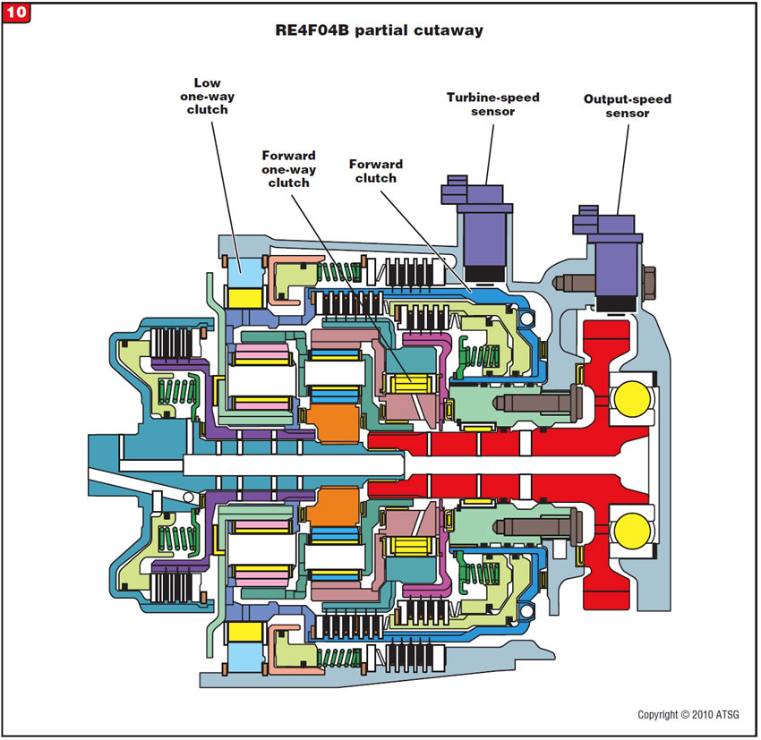
The reason the TCM detects no output speed is that there is no TSS reading when the transmission is in first gear. Refer to the partial-cutaway view of the RE4F04B in Figure 10. The OSS obtains its reading from the output gear, and the TSS obtains its reading from the forward-clutch drum. In first gear the forward-clutch drum is held stationary by the action of the low one-way clutch.
When installing the transmission make certain to connect the sensors correctly. Refer to the wiring diagrams in Figure 11 for wire-color reference.
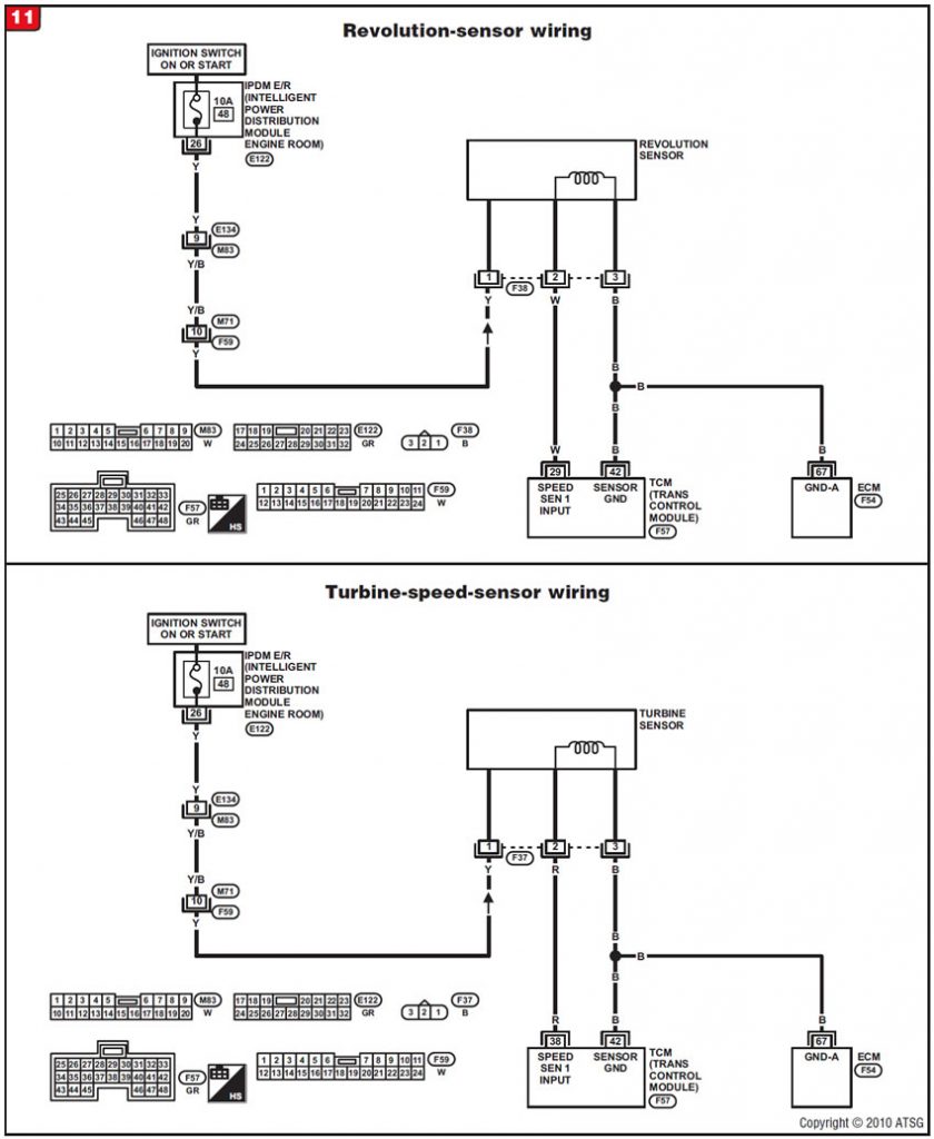
Note: Wire colors may differ among models and years. Consult the appropriate factory service manual for the vehicle you are working on. It may also be a good idea to tag the connectors before transmission removal to avoid cross-connection.


A vehicle with a ZF 5HP24 comes in with a complaint of little or no movement forward; reverse is good.
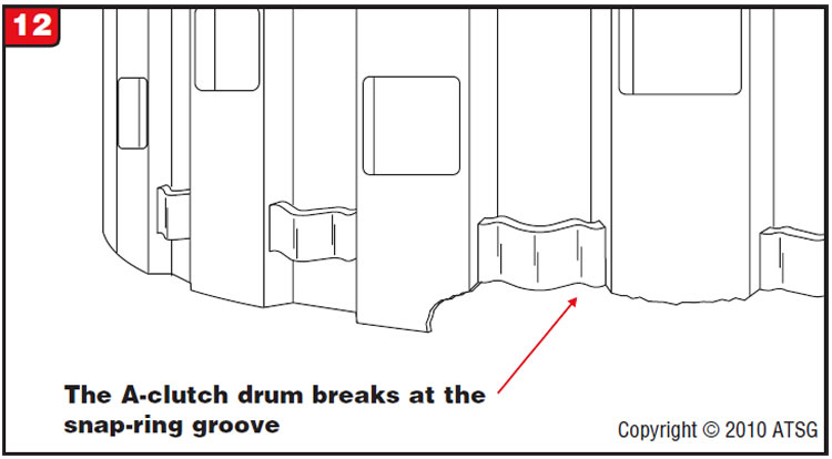
Upon disassembly of the transmission the A-clutch drum is found to be broken at the clutch-pack retaining snap ring (Figure 12) and the snap ring has come out of the drum.
The technician replaced the drum with the updated part only to have it come back with the same complaint and the drum broken again.
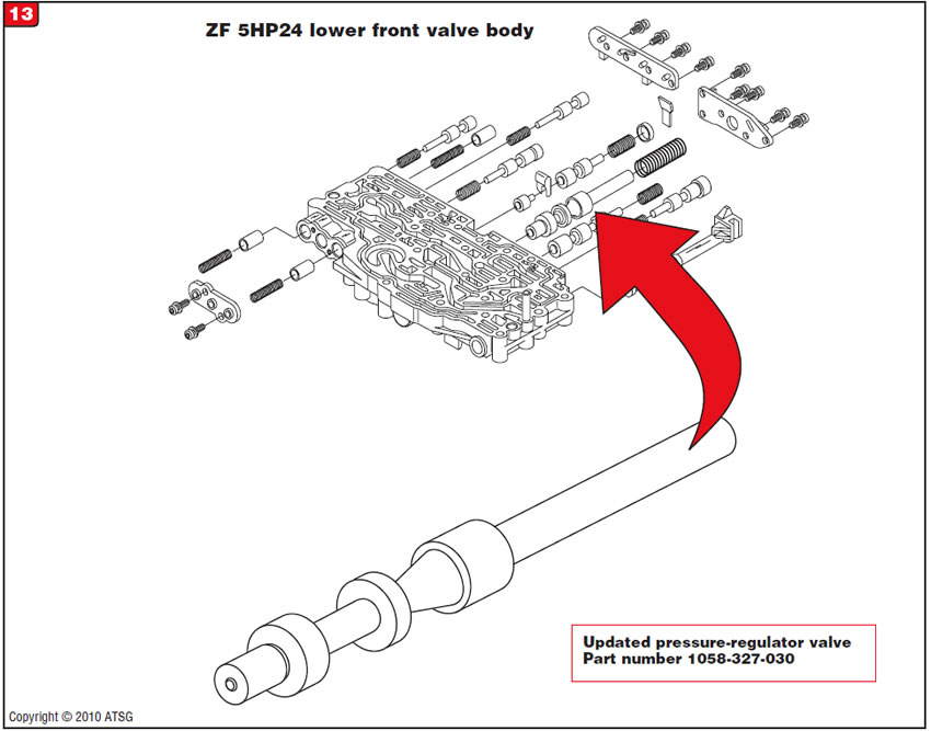
The drum is breaking in the snap-ring area because of un-commanded pressure spikes. There is an updated pressure-regulator valve (Figure 13) that could help the situation as long as the valve bore is not worn.
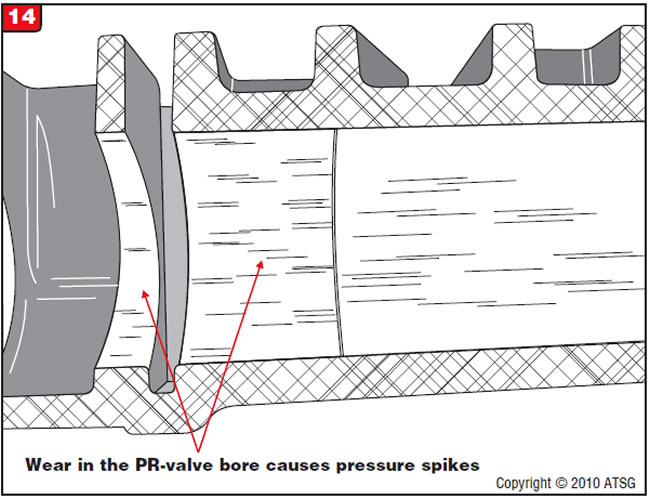
The pressure spikes can still occur and are caused by wear in the pressure-regulator-valve bore in the lower front valve body (Figure 14).
Using the part numbers provided here, replace the pressure-regulator valve and the lower front valve body.

- Updated A-clutch drum. . . . . . . . . . . . . . . 1058-270-040
- Updated pressure-regulator valve . . . . . . . 1058-327-030
- Lower front valve body . . . . . . . . . . . . . . . 1058-327-022

After an overhaul a Nissan/Infiniti vehicle equipped with the RE4F04B automatic transaxle exhibits a complaint that the engine stalls when the selector lever is placed into a forward or reverse gear and the vehicle accelerates from a stop.
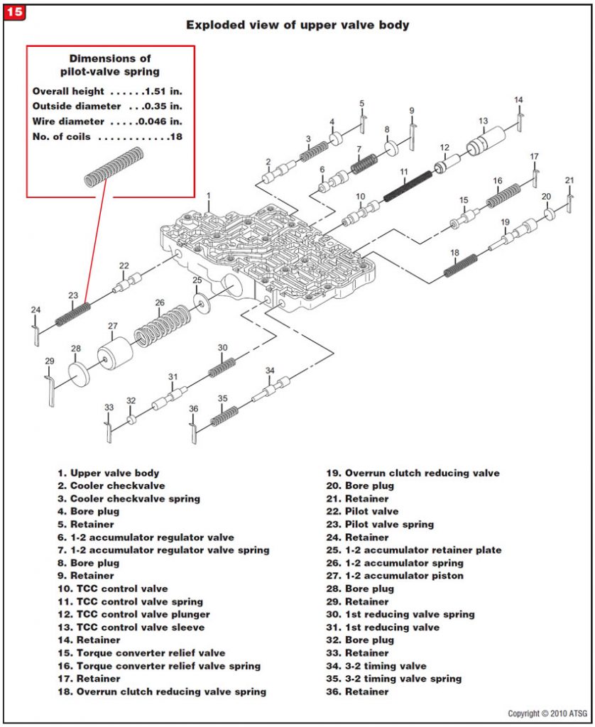
One cause may be that the tension of the pilot-valve spring is too heavy. The pilot valve in the RE4F04B is used to regulate oil pressure to the solenoids. If during overhaul the pilot-valve spring is replaced with a heavier one, increased pilot pressure will result. This means higher pilot pressure will be fed to the solenoids. If pilot pressure becomes too high, it can flood the TCC solenoid to the point that the TCC solenoid cannot exhaust enough pilot pressure to keep the TCC valve from stroking and applying the converter clutch during acceleration from a stop.
Use care when overhauling the transmission and choosing to change the pilot-valve spring. A spring that is significantly heavier than the OE spring may cause engine stall.
Refer to the diagram in Figure 15 for pilot-valve and spring location in the upper valve body, and use the spring dimensions provided as a guide during overhaul.

September 2011 Issue
Volume 28, No. 9
- Mitsubishi 3000GT: Sport Lamp flashing
- Nissan/Infiniti RE4F04B: No upshift; DTC P0720 may be stored
- BMW/Jaguar ZF 5HP24: Failure of A-clutch drum
- Nissan/Infiniti RE4F04B: Engine stalls during acceleration from a stop


