

Since the start of production for the 2006 model year, four-cylinder models of Ford Fusion, Mercury Milan, Lincoln MKZ and Zephyr, and Mazda 3 and 6 series have used a new version of the 4F27E/FN4A-EL transaxle known as the FNR5/5NR5.
This new transaxle has been redesigned to accommodate five forward ratios through a new intermediate gear set. This gear set has been split up into a planetary assembly capable of placing the pinion shaft into a reduction or 1-1 ratio. Mechanical control of the intermediate shaft is comprised of a reduction brake, a one-way roller clutch and a direct (5th) clutch. Hydraulic and electronic controls of this new gear set are under the pan on the side of the transmission.
The TCM monitors applications, gear changes and ratios with the added forward-clutch pressure switch and the intermediate-shaft speed sensor, which reads the driven transfer gear. The TCM has incorporated Electronic Synchronous Shift Control (ESSC), which provides greater adaptive control of the shift elements to avoid abrupt gear changes and downshifts. ESSC is also capable of adapting shift control as wear accumulates in the transaxle to prolong its life.
Refer to the accompanying illustrations to see the changes that took place in the electronics, gear train, the added valve body and the casing to make this possible.
Even though this unit is called FNR5/5NR5, the components providing the first four speeds are identical to those in the 4F27E with all the same aches and pains such as servo-bore wear causing slide shifts on the 2-3 and shift solenoid 2 or the bonded plate under the solenoid body causing a 3-neutral. So all the experience you gained with the 4F27E will not go to waste with the FNR5/5NR5.
Mechanical additions and operation
Figure 1 contains the shift-application charts for both of these transaxles.
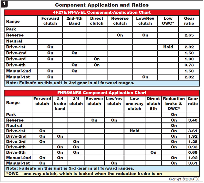
Figure 2 shows the 4F27E/FN4A-EL and FNR5/5NR5 for external identification and the location of the added intermediate-shaft speed sensor.
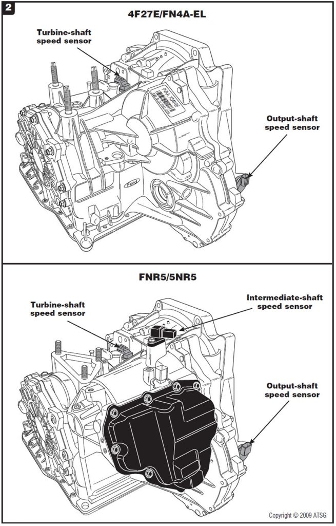
Figure 3 shows the location of the forward-clutch pressure switch and its function along with pressure-tap information on the front side of the case.
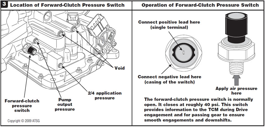
Figure 4 is an exploded view of the added intermediate shaft and all its components.
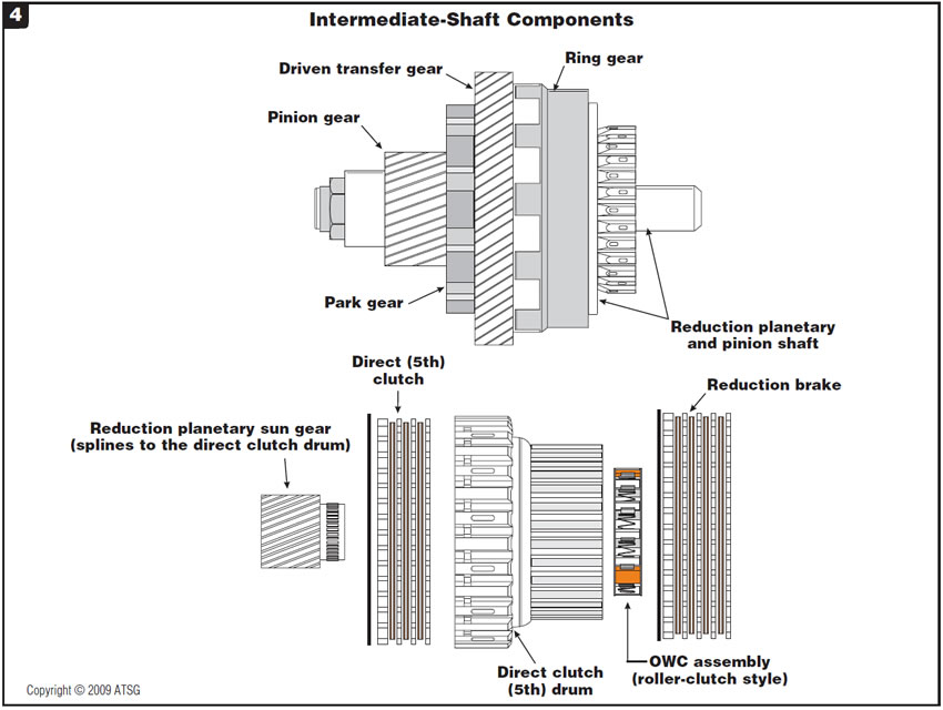
Figure 5 explains the power flow of this intermediate shaft in 1st, 2nd, 3rd and 4th reduction gears.
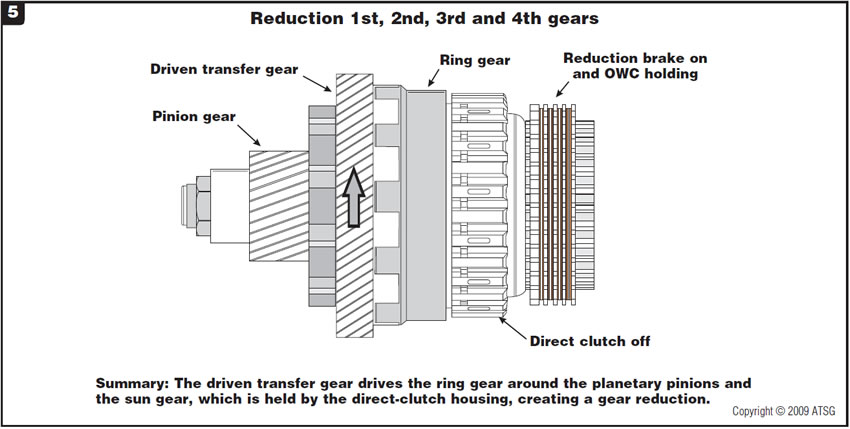
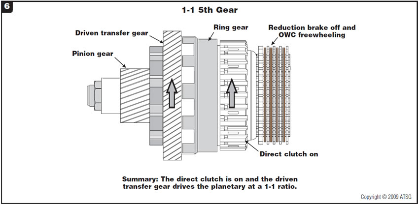
Figure 6 then shows the power flow of the intermediate shaft when it goes 1-1 for 5th gear.


Electronic and hydraulic additions and operation
Figure 7 shows the location of the added pressure-control solenoid B and shift solenoid F along with their resistance-test values.
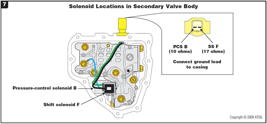
Figure 8 provides identification of passages in the secondary valve body.
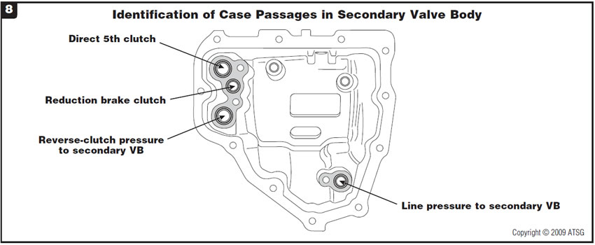
Figure 9 provides identification of passages in the main-case rear-cover side.
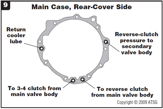
Figure 10 provides identification of passages in the rear cover.
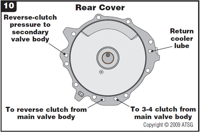
Figure 11 provides identification of passages in the main-case valve-body side.
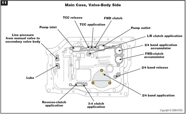
Figure 12 provides identification of passages in the secondary valve body.
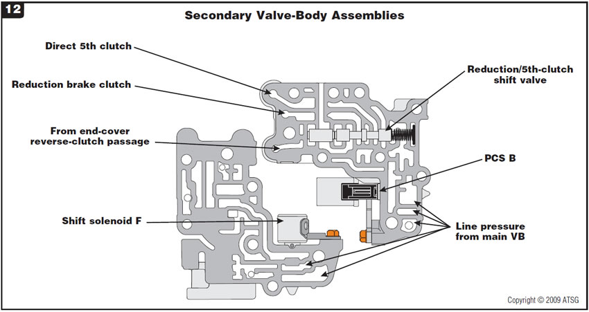
Figure 13 provides a hydraulic schematic of the secondary valve body in forward ranges 1st through 4th gears.
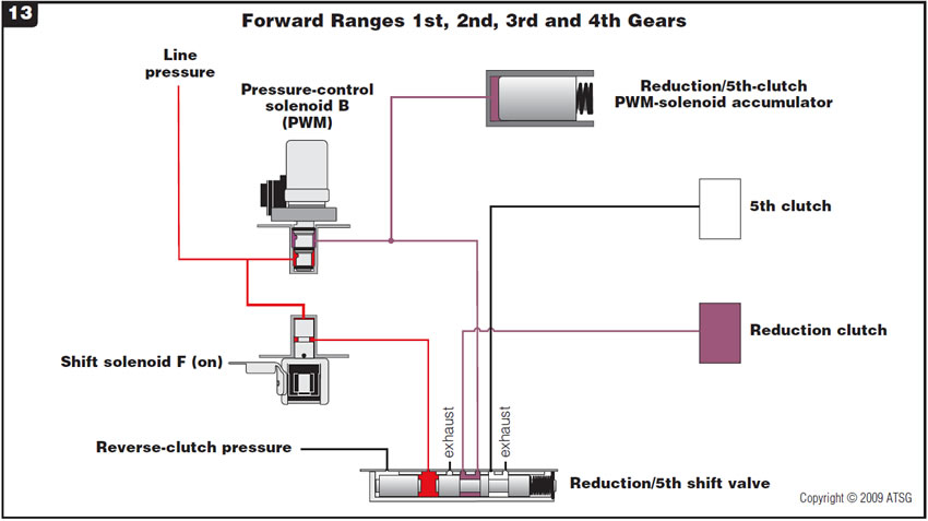
Figure 14 provides a hydraulic schematic of the secondary valve body in forward range 5th gear.
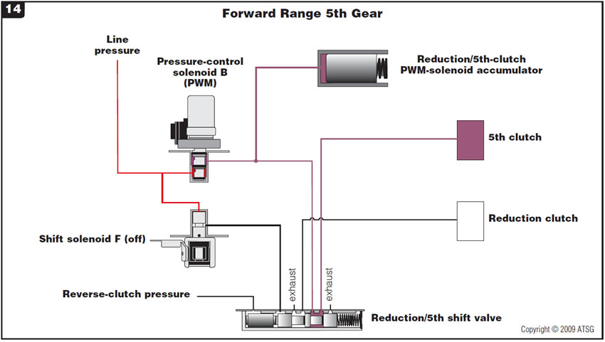
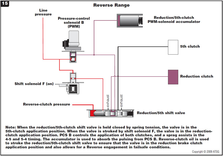
Figure 15 provides a hydraulic schematic of the secondary valve body in reverse range and a description of hydraulic flow.
Many thanks to the good folks at Alto for providing ATSG with an FNR5 transmission!


September 2010 Issue
Volume 27, No. 9
- Ford FNR5/Mazda 5NR5: Preliminary information


