Issue Summary:
- This month’s issue covers a variety of complaints on Mercedes Benz vehicles, including harsh reverse or delayed reverse engagement in 722.3, 722.4 & 722.5 units, and slipping on take-off on models equipped with the rear-pump-elimination kit.
- In AX4S/AXODE units, solenoid-wire connectors installed on the wrong solenoids may cause harsh shifts, a clicking noise and tie-up on shifts.
- We have listed the vehicle-harness repair kits that are available for several different Ford transmissions.
- Failure of the exhaust-brake system on Isuzu NPR/GMC Forward Tiltmaster vehicles could be caused by elevated line pressure and premature transmission failure.


(1) Harsh reverse engagement hot or cold, before and/or after overhaul.
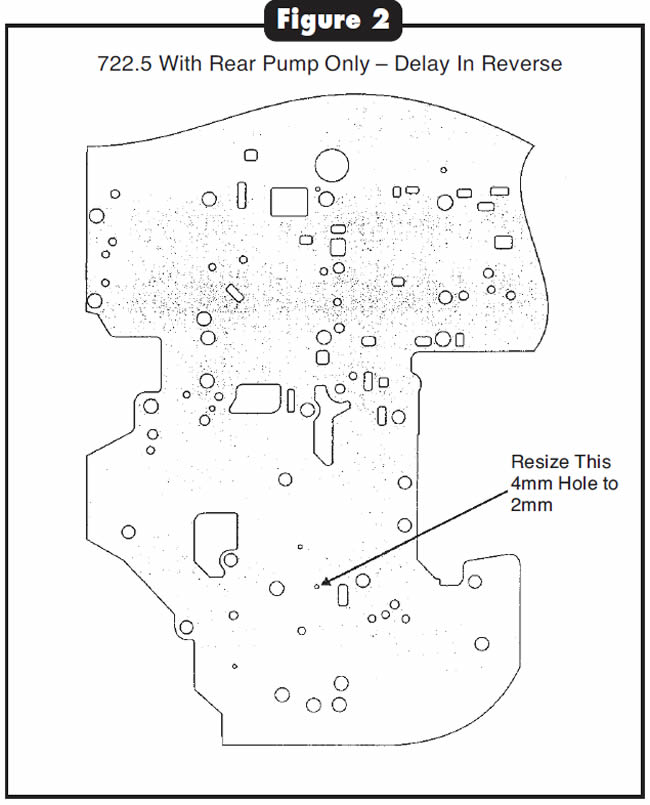
(2) Delayed reverse engagement on 722.5 with rear pump, hot or cold, before and/or after overhaul.
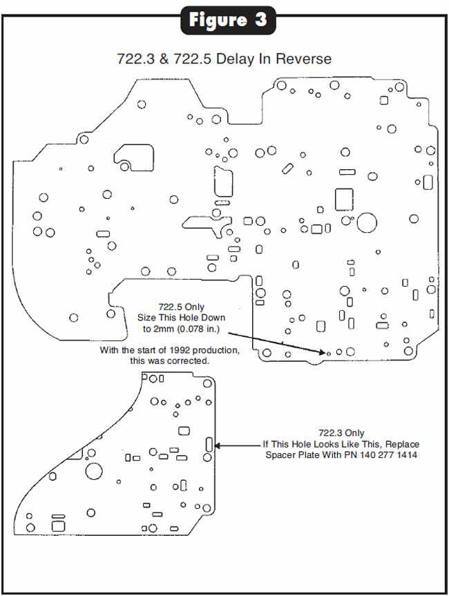
(3) Delayed reverse engagement on 722.3 and 722.5 without rear pump, hot or cold, before and/or after overhaul.

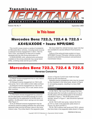
(1) The harsh reverse engagement is a result of the flat steel plate not providing enough of a cushioning effect for the application of the B3 clutch. In addition, the B3 piston-return springs are too weak.(See Figure 1)
(2) & (3) Delayed reverse engagement may be caused by pressure leaking between the valve-body separator plate and the KS drain valve in the transmission case. The orifice feed in the separator plate shown in Figures 2 and 3 was made too large (4mm) by the manufacturer.
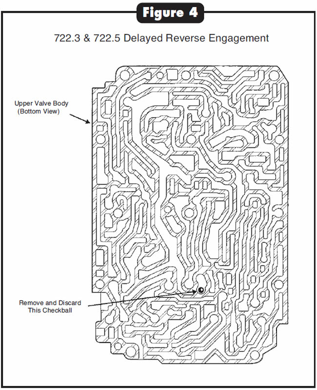
Delayed reverse engagement also may be caused by the checkball in the valve body, shown in Figure 4, not seating properly, resulting in a loss of B3 apply oil.

- (1) On 722.3, 722.4 and 722.5 replace the thick flat steel plate that normally is positioned on top of the B3 piston with the dished plate in the direction indicated in Figure 1. The 20 B3 piston-return springs, shown in Figure 1, also should be replaced at this time.
- (2) On 722.5 with rear pump, reduce the 4mm (0.157-in.) hole in the separator plate shown in Figure 2 to 2mm (0.078 in.).
- (3) On 722.5 without rear pump and 722.3, reduce the 4mm hole in the separator plate shown in Figure 3 to 2mm. If your separator plate has the large hole shown in Figure 3, replace the separator plate.
If the vehicle is a 1992 or later, the manufacturer has corrected this problem.
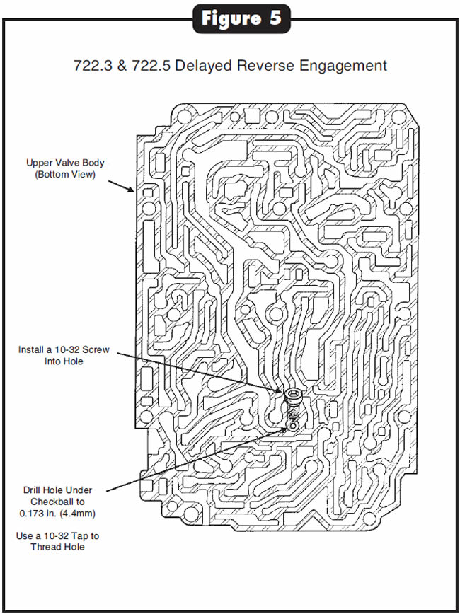
On 722.3 and 722.5, discard the checkball shown in Figure 4 and enlarge the hole in the bottom of the checkball pocket to 0.173 in. (4mm).
Then tap the hole for a 10-32 machine screw and insert the screw into the threaded hole (See Figure 5).

- B3 Dished Plate for 722.3 and 722.5 …………………….140 993 1526
- B3 Dished Plate for 722.4………………………………201 993 0926
- 722.3/722.5 Package of 20 B3 Piston-Return Springs ………………………………………………………….126 993 2702
- 722.4 Package of 20 B3 Piston-Return Springs…..123 993 4401
- 722.3 Separator Plate…………………………………..….140 277 1414
- B3 Reverse Delay Kit containing a drill bit, a 10-32 tap, 10 10-32 allen-head machine screws and an allen wrench…………Mario Aristides
Thanks to Mario Aristides for his technical assistance in compiling this information.


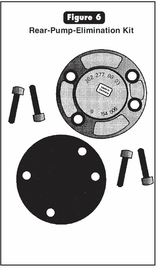
After installation of a transmission that is equipped with a rear-pump-elimination kit (See Figure 6), the transmission exhibits slipping on initial take-off.
The lower-cover section of the valve body still contains the secondary-pump shift valve (See Figure 7). When this valve strokes, it allows B2 apply oil to exhaust, which causes the transmission to slip on take-off. This directly affects the application of the B2 band, which is necessary for forward movement.
Install the aluminum plug shown in Figure 7 in place of the secondary-pump shift-valve train, using only the retainer and the aluminum plug.
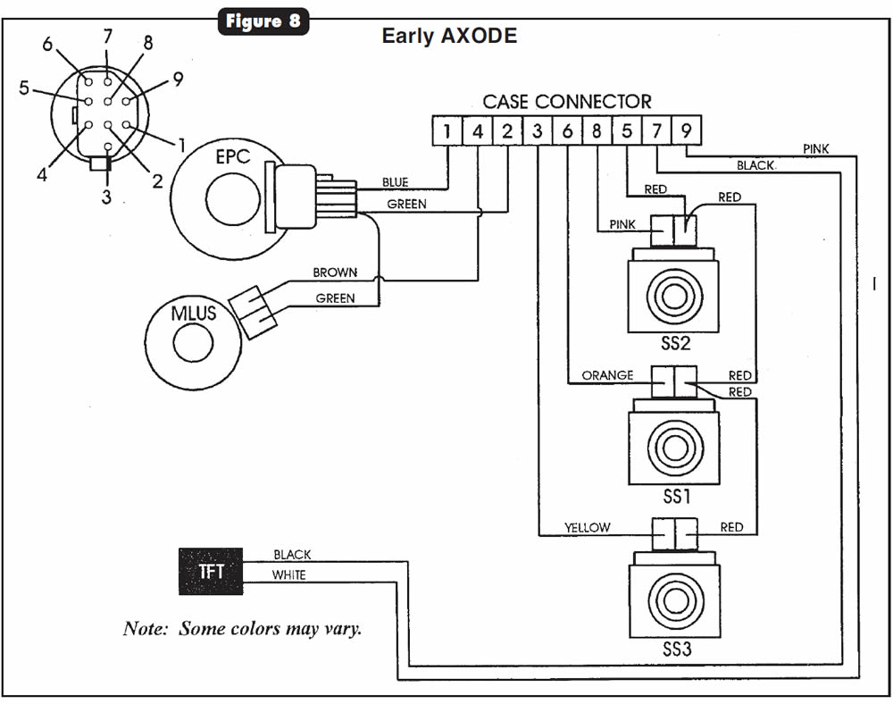
After rebuild, the unit may have harsh shifts (high line pressure) and/or a clicking or cycling noise from the side-cover area, usually accompanied by an on/off bind-up sensation that coincides with the clicking noise. These symptoms may be accompanied by diagnostic trouble code (DTC) 652 (MLUS shorted or open circuit), 624 (EPC circuit failure) and/or shift-solenoid DTC 621, 622 or 624.
The cause may be solenoid-wire connectors installed on the wrong solenoids.
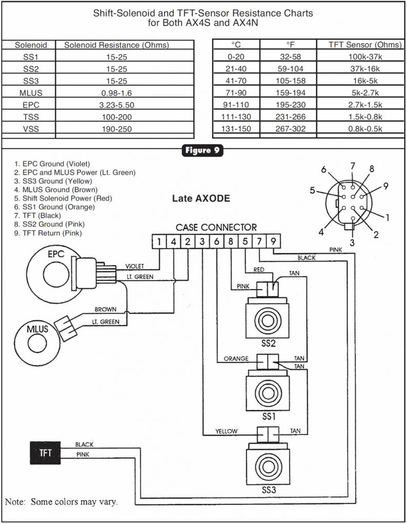
Attach the connectors of the internal wiring harness to their proper solenoids, using as a guide the wire colors shown in Figures 8 and 9. You also can verify proper connection of solenoids externally through the case connector using the resistance chart in Figure 9.
Note:
The internal wire harness normally is secured by wire ties, which would prevent improper connection of solenoids. However, not all wire harnesses have the wire ties necessary to prevent this problem, and the chart is necessary in those instances.

Ford Motor Co. has made available vehicle-harness-connector repair kits for several different transmissions and locations. We have listed the OEM part numbers and some illustrations (Figures 10-13) of the contents of the service packages that are available.
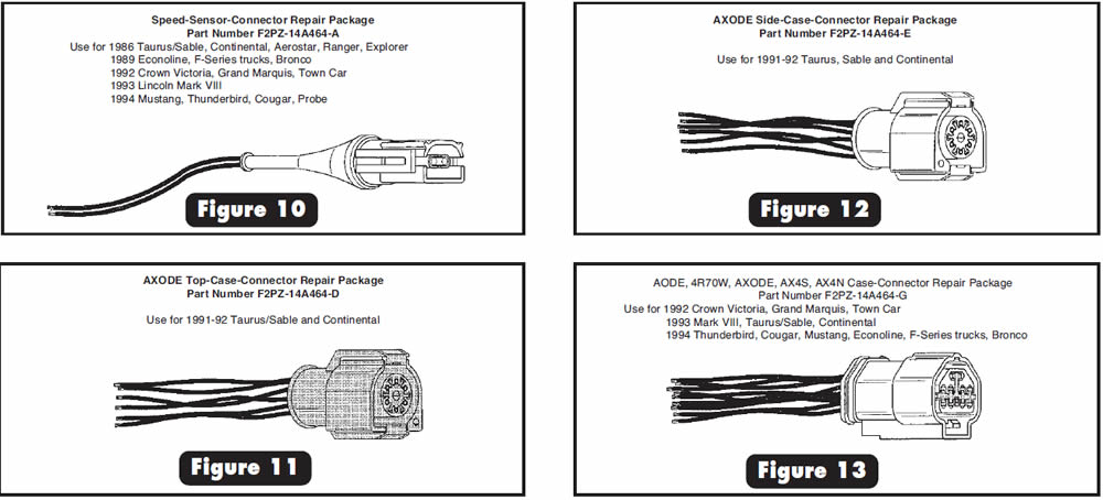
- Speed-Sensor-Harness Repair Package (Various Models) {Figure 10} …………………………….F2PZ-14A464-A
- Case-Connector-Harness Repair Package (E4OD)……………………………………………….F2PZ-14A464-B
- MLP-Sensor-Harness Repair Package (Various Models) …………………………………………F2PZ-14A464-C
- Top-Case-Connector-Harness Repair Package (’91-92 AXODE) {Figure 11} …………………………F2PZ-14A464-D
- Side-Case-Connector-Harness Repair Package (’91-92 AXODE) {Figure 12} ………………………..F2PZ-14A464-E
- Case-Connector-Harness Repair Package (’86-90 AXOD) ………………………………………..F2PZ-14A464-F
- Case-Connector-Harness Repair Package (AODE, 4R70W, AXODE, AX4S, AX4N) {Figure 13} …………….F2PZ-14A464-G

Possible complaints due to failure of the exhaust-brake system include elevated line pressure, premature transmission failure, poor engine performance and slow cab warm-up.
First, an explanation of how this system operates is in order to better understand the causes of the complaints.
A large driving force is applied to the various clutches and bands, especially the overrun clutch, in the transmission when engine braking is required. If additional help were not available, these clutches and bands would fail prematurely. One of the functions of the exhaust-brake system is to use exhaust backpressure to help slow the truck, thereby helping the transmission to do its job of engine braking with-out unnecessary damage.
Activating the exhaust brake, which is controlled by a switch on the dashboard, raises line pressure. An engine warm-up switch on the dashboard also activates the exhaust brake.
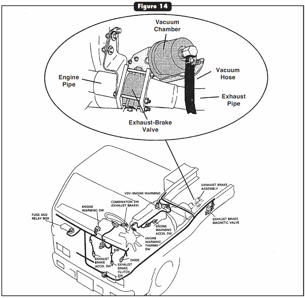
The exhaust brake uses a vacuum-operated valve between the engine pipe and the exhaust pipe (See Figure 14). The exhaust brake is activated by a magnetic valve attached to the driver-side frame rail.
Note:
The magnetic valve is not used when the exhaust brake is activated by the engine warm-up switch.
The exhaust-brake system also provides for rapid cab warm-up in cold weather.
If the exhaust-brake system is electrically stuck on, line pressure will be higher than normal. If the exhaust brake is mechanically stuck closed, the engine will perform poorly. If the exhaust brake is inoperative or not used, premature transmission failure can result.
When activated, the exhaust brake sends a 12-volt signal to the TCM, which in turn initiates line-pressure-control strategy for the exhaust brake. When the exhaust brake is off, it sends no voltage to the TCM.
You can check this signal at the TCM with a volt-meter. Check to see whether the exhaust-brake valve is stuck shut, and ensure that the vacuum diaphragm holds vacuum and the magnetic valve is working.

September 2001 Issue
Volume 18, No. 9
- Mercedes Benz 722.3, 722.4 & 722.5: Reverse Concerns
- Mercedes Benz 722.3, 722.4 & 722.5 With Rear-Pump-Elimination Kit: Slipping on Take-Off
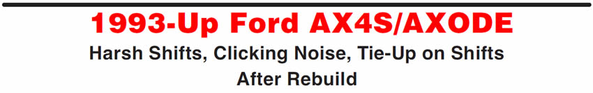
- 1993-Up Ford AX4S/AXODE: Harsh Shifts, Clicking Noise, Tie-Up on Shifts After Rebuild
- Ford Vehicle-Harness-Connector Repair Kits Available
- Isuzu NPR/GMC Forward Tiltmaster: Exhaust-Brake Operation


