Technically Speaking
- Author: Mike Riley, Technical Editor
- Subject Matter: Automatic transmission
- Issue: Sealing rings
There have been many ways to plug a hole (so to speak), and sealing rings are but one. These small pieces of metal, or other material, have been part of the automatic-transmission landscape since inception. A transmission could not work without them, even though a few applications have used a bushing to seal oil pressure.
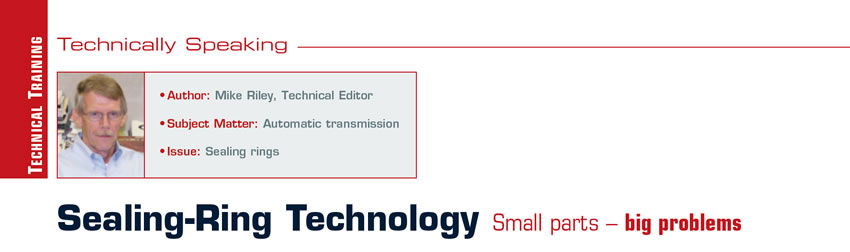
A sealing ring works by filling the space between an item and the bore that surrounds it in a manner that prevents loss of oil pressure. Sealing rings, no matter the design or material, basically function the same. As pressure exits a passage and enters the chamber where a sealing ring is needed, such as a servo piston and case bore or stator support and clutch drum, a couple of things need to happen. The sealing ring is stroked (pushed) away from the pressure source and against the ring-groove sidewall, creating a seal on the outside face of the ring. In addition, pressure is directed under the ring, creating an outward force against the bore to provide a seal at the ring outside diameter and bore inside diameter (Figure 1).
If a condition existed to prevent either of the functions from happening, pressure could escape and bad things would happen. For instance, if particles (debris) became wedged between or embedded in a sealing ring, the space created between the ring and groove would allow pressure to escape. If a ring-groove sidewall would become dinged (indented) or burred because of contact with the component bore, the same result would occur. Ring-groove sidewalls must be square, flat and smooth or pressure will be lost. Ring wear will happen quickly as well.
If the sealing-ring bore is tapered or out of round, then the oil pressure will escape (leak) at the ring O.D./bore I.D. Based upon sealing-ring operation, the ring (in most instances) must remain with the bore, meaning that if the ring bore – such as in a clutch drum – rotates, the ring must rotate as well. If the bore is stationary, such as a case bore, the ring must be held stationary to boot, meaning that only the ring groove rotates.
If the scenario changes and the ring “sticks” to the ring groove, pressure will cause the ring to wear into the bore as well as wearing the O.D. of the ring. Proper bore microfinish is important to enable the ring to bite (stick with) the bore and prevent wear. Ring wear at the bore is different from ring-land wear, which results from the bore contacting the ring land (groove) due to excess endplay or bushing clearance. All components must work together to provide a good seal.

As with everything, there are exceptions. Sealing-ring development is dependent on a few things such as material, coatings, joint designs, edge and face design, production cost and installation concerns as well as drag co-efficient and durability.
The first modern sealing rings to be used in automatic transmissions were, of course, “black iron” powered-metal rings. The rings were used everywhere, in static and dynamic applications, and had a lube rite coating that would dissipate with usage, exposing the shallow machine marks. Black iron rings could have an interlock or butt joint and when installed into the bore required the proper ring-joint clearance. The outside-diameter edges could be squared or chamfered. Rings with chamfered edges installed more easily but were more costly to produce.
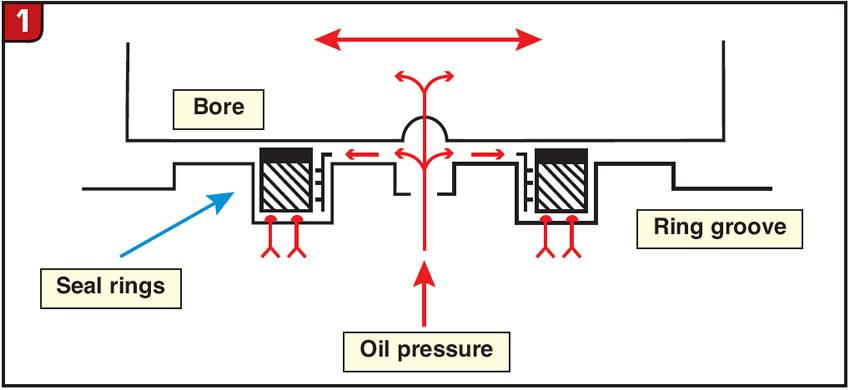
To address specific wear issues over time, different production processes were implemented, such as the white tin/nickel coating on A727 stator rings or development of “seal plate” (gray) sealing rings, such as AODE output rings (Figure 2).
Rebuilders love metal rings because of the ease of air-checking clutch packs etc. This is because metal rings basically self-energize to seal what’s necessary. Unfortunately, metal rings are history, since newer transmission models use other materials.
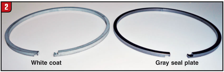
The first sealing-ring material alternative to displace metal rings was Teflon. Manufacturers started to change to Teflon for different reasons, but cost was a main factor. One of the first lessons that the OEMs learned was that Teflon and aluminum don’t necessarily work well together. Case in point: The sun-gear-shaft to output-shaft-tube rings were changed to Teflon in the mid-’60s on the Ford CIC transmission, and ring wear of the tube happened pronto (Figure 3). Even a more static application like a Mitsubishi servo-piston ring would eat the case in short order due to the wrong composition.
This is because not all Teflon is created equal. Teflon materials vary in how they are made. One Teflon ring could have a high content of glass filler while another has a higher percentage of graphite. Ring composition will dictate how quickly the ring or component might wear. The OEMs try to pick the best combination but could miss at times. Ring color or markings sometimes denote composition; for example, a white ring usually has a high percentage of glass filler and should not be used with soft adjacent parts (Figure 4).

Teflon rings can be produced with a scarf-cut or butt-cut joint; others may be solid, requiring an expander/sizing tool. There are also Teflon rings with a step joint. Ring material and processing will dictate the style of joint, if any. Domestic manufacturers mainly opted for scarf cutting, which is more forgiving with tolerances, while Asian manufacturers would use more butt-cut applications. To provide a consistent butt-cut ring that does not shrink (increase gap) over time requires a different process, including turning the I.D. and O.D. of the initial tube and then stress-relieving it before the butt cut. Making a butt-cut ring without this approach can result in heat shrinkage, as was evident when domestic rings were produced for G4A EL and F4A EL models years ago. The folks at TransTec realized the manufacturing variables and took steps to provide the proper rings for transmission models like the G4A EL and F4A EL.
Arbitrarily moving Teflon rings around is probably not a good idea, long term. Teflon rings also do not air-check as well as metal because they don’t self-energize like metal rings. Always maintain the air pressure while rotating and wiggling a drum or shaft, which could help with the air check.
More recently, ring material is plastic (or so it would appear). The reality is that rigid sealing rings are made from different materials and produced with different processes.
Just shy of three decades ago, a significant change in sealing-ring technology emerged in the form of Vespel by DuPont. Not only was the material different but it also differed in how it would function. Unlike previous-design rings that would rotate in the ring groove, the 1987 GM 4T60 second-clutch Vespel rings were tanged, preventing them from rotating in the groove. Beyond that, a rubber quad ring was used between the Vespel ring and drum support, creating a static compression seal. At first glance, it would seem that either the Vespel rings or the drum bore would be toast in no time, but such was not the case due to the properties in Vespel – “dynamite.” The quad rings were omitted in 1998; however, the Vespel rings remained tanged.
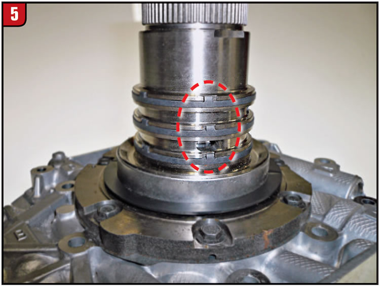
The 6L80 was launched in 2006 with rotating Vespel, but for some reason GM needed a tweak and switched to a tanged stationary design (Figure 5). Time will tell whether premature drum-bore wear occurs. Vespel tends to be green for transmission applications.
A less-costly alternative to Vespel is a material called Peek. As with Vespel, Peek can be produced in different forms and shapes. Joint design can also vary from a butt joint to a step joint.
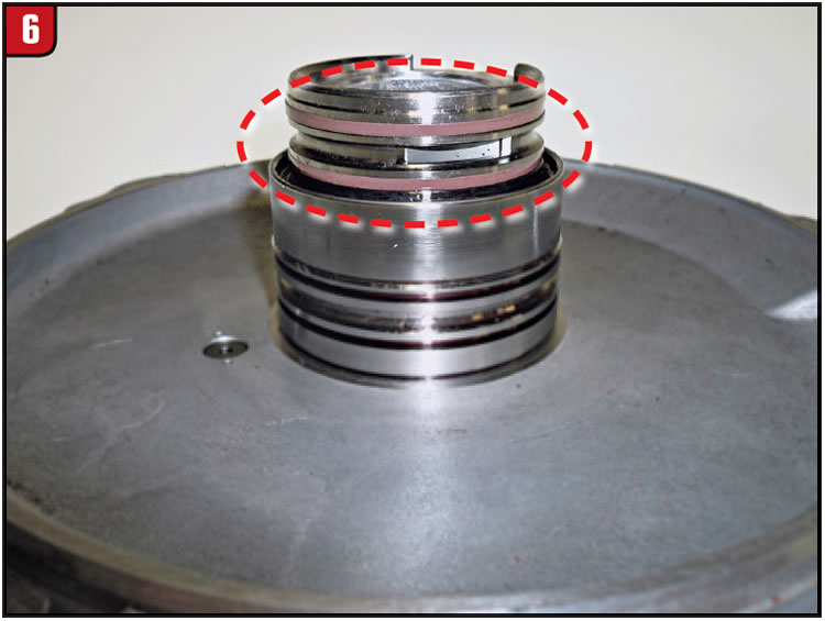
Manufacturers choose sealing-ring designs for different applications, which don’t always work out. In 1999/2000, Mazda and Ford released the 4F27E. Mazda chose to make the end-cover ring lands aluminum. Ford used a steel sleeve (Figure 6).
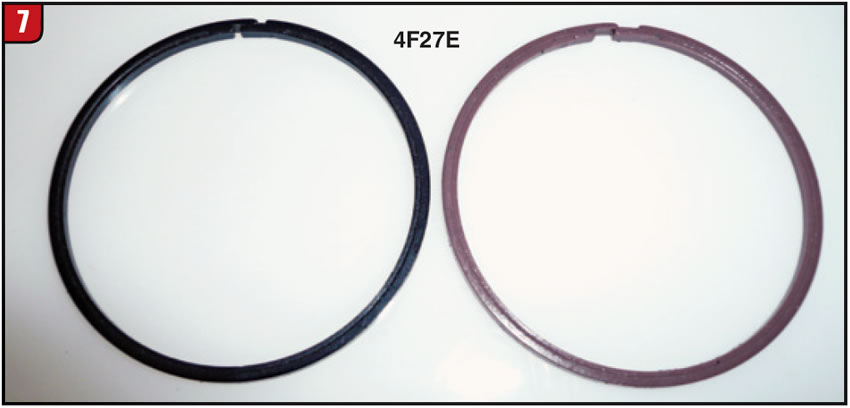
Guess which one failed. From experience, Ford knew better than to use rotating rings in aluminum parts. There have even been two different colors for the same position (Figure 7).
Torlon is another material that fits into the plastic category and has different properties from Vespel or Peek. Many valve-body checkballs are made with Torlon, which is a robust option.
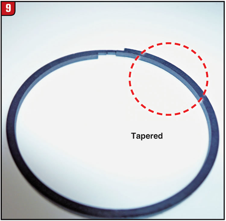
Ring wear is always a concern, and to limit sidewall wear, manufacturers have taken different approaches. A sidewall could be scalloped or have V grooves to increase lubricity. For instance, the Toyota U150E end cover has a unique-style ring (Figure 8).
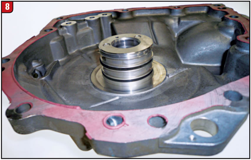
The inner edge is narrower than the outer edge, creating a taper for a better oil cushion (Figure 9).
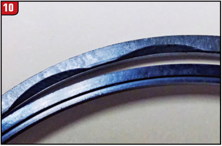
Another design option could be a step in the ring face (Figure 10).
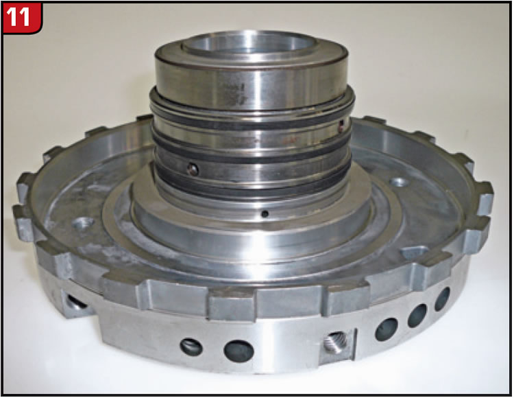
The Nissan RE5R05A center support has experienced ring-groove wear, and choosing a good replacement material is a challenge because of size limitations (Figure 11).
Honda has also had some wear issues, and the engineers at Precision International identified a deficiency in the processing of the rings. Certain rings could have rough edges that would lead to premature wear of the aluminum bores. Precision uses a tumbling process to ensure smooth edges with no burrs. Even plastic material can be tough.
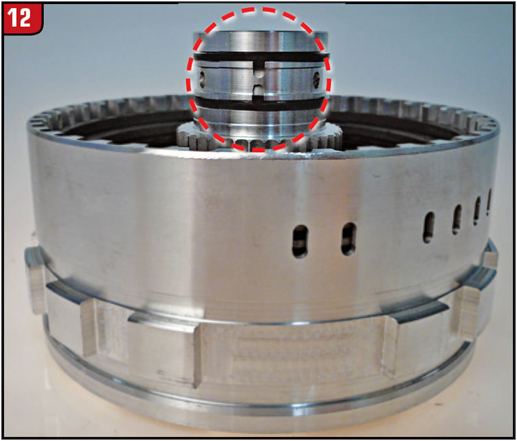
Another example of ring-groove wear in a later-model transmission is the 62TE compounder’s low drum. Chrysler just recently changed the ring design and added a tang to prevent rotation, just as GM did back in the old days (Figure 12).
Sealing-ring issues are not limited to the USA. Transmissions used internationally can also have ring problems, such as the Renault DPO, which was limited to Europe initially. More recently DPO usage has expanded to China and South America. A DPO could have an issue of losing drive when coming to a stop once hot.
The product specialists at Seal Aftermarket Products reviewed the condition to determine the cause and found that the ring joint needed attention. They changed the ring from a butt joint to a modified step-joint design to accommodate temperature changes. The E1 clutch held more pressure with the new-design ring. Upgrading sealing rings requires time and effort.
The more things change, the more they stay the same.


