Revisiting the Captive Clutch - Transmission Digest

Revisiting the Captive Clutch

Joe Rivera proved that the ZF 5HP19/24 converter with captive clutch is rebuildable (see “Rebuilding the Unrebuildable,” Transmission Digest, December 2005). Many converter shops are now trying to build this unit, and the number of rebuilding questions continues to increase. A recent rise in issues related to lockup performance after rebuild has prompted a closer look at this unit. The same fear factor that prevented many shops from trying to rebuild this unit in the first place is now causing some of the braver rebuilders to have second thoughts.

Revisiting the Captive Clutch

Torque Converter Tech Tips

Author: Ed Lee

Torque Converter Tech Tips

  • Author: Ed Lee

Joe Rivera proved that the ZF 5HP19/24 converter with captive clutch is rebuildable (see “Rebuilding the Unrebuildable,” Transmission Digest, December 2005). Many converter shops are now trying to build this unit, and the number of rebuilding questions continues to increase. A recent rise in issues related to lockup performance after rebuild has prompted a closer look at this unit. The same fear factor that prevented many shops from trying to rebuild this unit in the first place is now causing some of the braver rebuilders to have second thoughts.

A better understanding of the mechanics that make this converter unique should ease some of their concerns.

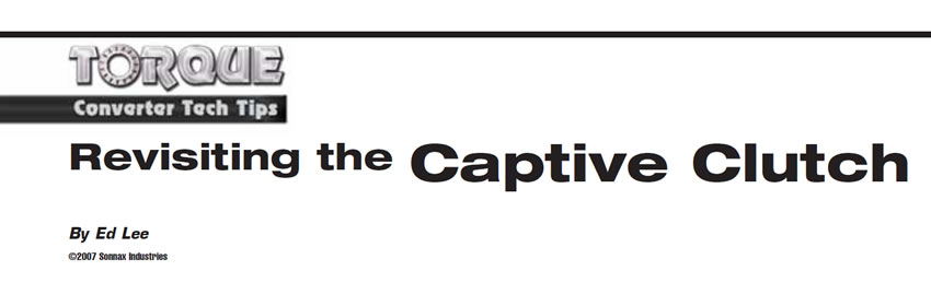
The most-unusual part of this converter is the TCC piston’s extremely limited range of travel. The six springs that aid the forward movement of the piston are riveted to the piston on one end and the spring retainer on the other end. Since the spring retainer is friction-welded to the center tower of the converter and no provision has been made for extra travel, the piston can travel only as far as the spring can flex. This limits the total available travel of the piston to 0.040 inch. To put this into perspective, 0.040 inch is 1 millimeter, or the thickness of a dime. Looking at the piston and retainer from the bottom of the piston, the gap that you see between the piston and retainer is its available travel (see Figure 1). Place the clutch on the cover and the piston on the clutch. You can now measure the position of the spring retainer in relationship to its position before it was removed.

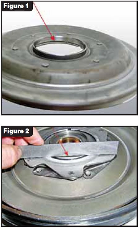
You will see that this converter was built with 0.010 inch of clutch-release clearance (see Figure 2). If you subtract the 0.010 inch of clutch-release clearance from the 0.040 inch of available travel, you will have only 0.030 inch of friction-material wear before the clutch runs out of travel and will no longer hold. This is why correct clutch-release clearance is so important.

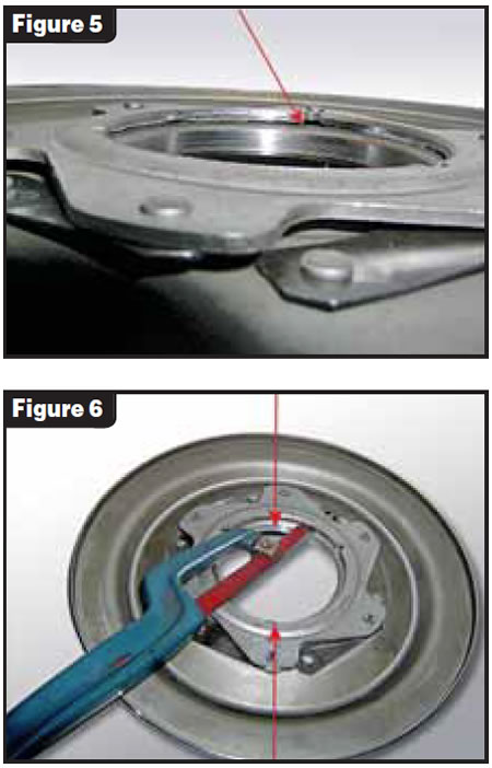
There are a number of different ways to set your clutch-release clearance. Place the cover on an arbor press. With the clutch and piston in the cover, depress the retainer down until it comes in contact with the piston (see Figure 3). This is the point of zero clearance and zero travel for the piston. With a dial caliper in contact with the piston and retainer, zero the dial. Now, allow the retainer to move up 0.010 inch (see Figure 4).

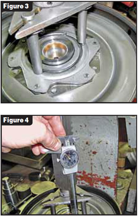
Welding the retainer in this position will give you the proper release clearance. Another way to achieve the same result would be to start with a dial indicator on the retainer and depress the spring retainer down until it traveled 0.030 inch, leaving 0.010 inch clearance. A third way would be to place a 0.010-inch shim stock between the piston and retainer from the outside and depress the retainer down until it rests on the shim stock. Weld the two retainer parts together and then remove the shim stock. If the gap between the mating parts of the retainer is as wide as shown in Figure 3, you may want to use brass shim stock so the weld doesn’t stick to it. The gap shown in Figure 3 was made by using a standard 1/8-inch cut-off tool. If you use a cut-off tool, grind a 45° angle on the end and cut with the long side next to the converter tower. This will minimize your gap. When you cut the retainer, you must deburr the bottom side.

The retainer in Figure 5 has a burr that extends down 0.035 inch from the underside. This piston has only 0.005 inch of travel remaining and will not release. A hacksaw blade with a handle does a good job of restoring the correct gap (see Figure 6).

Remember from Joe Rivera’s article that the retainer must be cut to a diameter of 2.950 inches so that the piston will clear the part of the retainer that remains attached to the tower. Also remember to put the angle on your cut-off tool to minimize your weld. The most-important thing to remember is to take your time with the weld. Alternate your small welds around the circumference of the area to be welded.

Ed Lee is a Sonnax technical specialist who writes on issues of interest to torque-converter rebuilders. Sonnax supports the Torque Converter Rebuilders Association. Learn more about the group at www.tcraonline.com. ©2007 Sonnax Industries Inc.

You May Also Like

Sherlock Holmes Approach to an AB60 No-Move Situation

The effectiveness in diagnosing automatic transmission malfunctions is an art form. Although there are similarities among the wide varieties of transmissions on the road, each transmission has its own peculiarities. Aside from having mechanical, hydraulic, and electrical hardware systems to contend with, software/programming issues and various vehicle platforms make diagnostics much more difficult.  Using scopes provides

ab60

The effectiveness in diagnosing automatic transmission malfunctions is an art form. Although there are similarities among the wide varieties of transmissions on the road, each transmission has its own peculiarities. Aside from having mechanical, hydraulic, and electrical hardware systems to contend with, software/programming issues and various vehicle platforms make diagnostics much more difficult. 

GM 6T40 Pump Identification Guide

The 6T40 was introduced in 2008 for General Motors front-wheel-drive cars in the Chevrolet Malibu and has gone through several changes throughout its three generations, specifically in the pump area. The 6T40 is closely related to the more lightweight 6T30 and the heavier duty 6T45 and 6T50. Generation one started phasing out during the 2012

Seeing the Forest AND the Trees

They say that the proverbial phrase “I couldn’t see the forest for the trees” means that a person or organization cannot see the big picture because it focuses too much on the details. Related Articles – 4L60E Harsh 1-2 Shift – TASC Force Tips: Diagnosing 8L45 & 8L90 Shift Complaints – TASC Force Tips: Hydraulics

The Manifold Pipeway

The Honda six-speed transmission has been on the bench of many specialty shops for one reason or another (figure 1). But, for those of you who have yet to lay your hands on one, mounted on the upper side of the unit is one of the largest, if not the largest solenoid and pressure switch

8L90 Vacuum Testing

Below are the diagrams for vacuum testing GM 8L90 transmissions. Note: OE valves are shown in rest position and should be tested in rest position unless otherwise indicated. Test locations are pointed to with an arrow. Springs are not shown for visual clarity. A low vacuum reading indicates wear. For specific vacuum test information, refer

Other Posts

Critical Wear Areas & Vacuum Test Locations for FORD 6R80/6R100

Note: OE valves are shown in rest position and should be tested in rest position unless otherwise indicated. Test locations are noted with an arrow. Springs are not shown for visual clarity. Low vacuum reading indicates wear. For specific vacuum test information, visit www.sonnax.com. Related Articles – Hydraulics Fundamentals: Shift & Relay Valves – Another

Hydraulics Fundamentals: Shift & Relay Valves

Shift valves and relay valves share a lot of the same duties. This article is one of a series by Sonnax exploring how valves and hydraulic circuits work and what results when they quit functioning correctly.

Another 62TE ‘No-Move’ Possibility

Most seasoned techs have several quick diagnostic steps they take when faced with a transmission malfunction. The type of problem and transmission determines which steps to take. For example, a “no-move” condition. Related Articles – Ford 8F35 maintenance tips: Planetary failure and no-pressure conditions – Don’t fear customer complaints about CVTs – Shift Pointers: A Chrysler

Hydraulics Fundamentals: Clutch Regulator Valves

Knowing how these circuits work and the slightly different variations that the manufacturers utilize should pinpoint any valve body-related issues